


21
PLEASE NOTE: During routine servicing and
after any maintenance or change of part of
the combustion circuit, the following must
be checked:
- The integrity of the flue system and the
flue seals
- The integrity of the boiler combustion cir-
cuit and relevant seals.
- The operational working gas pressure as
described in section 4.7.1
- The combustion performance as descri-
bed in section 4.8.1
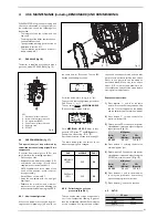
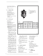
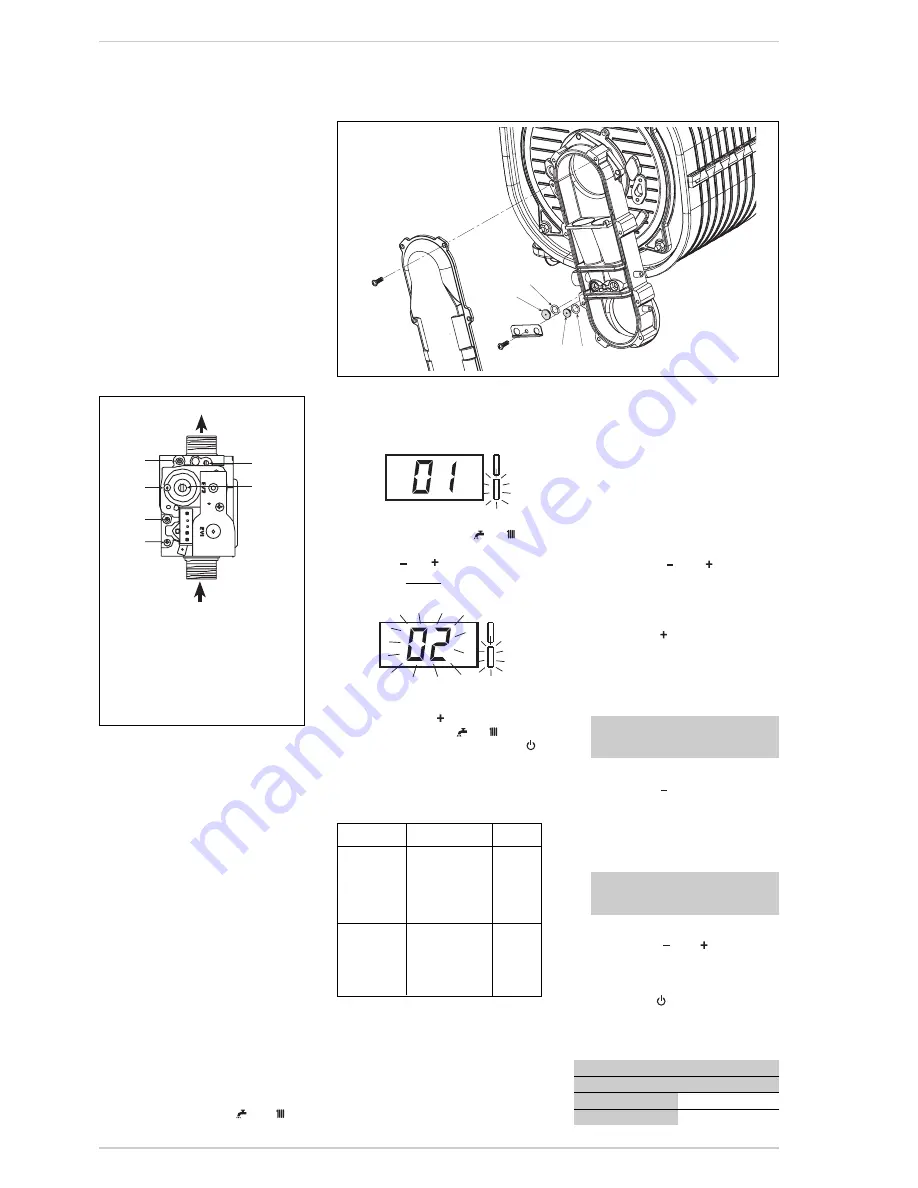
4.1
GAS VALVE (fig. 16)
The boiler is supplied as standard with a
gas valve, model SIT 848 SIGMA (Fig. 16).
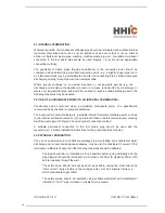
4.2
GAS CONVERSION (fig. 17)
This operation must be performed by
authorised personnel using original Sime
components.
To convert from natural gas to LPG or vice
versa, perform the following operations
– Close the gas cock.
– Replace the two differential nozzles (1-2)
and relative seal o-rings (3) with those
supplied in the transformation kit.
NOTE: the difference in the shape of the
head of the nozzles, avoid r ever sal
during assembly.
– Reset PAR as shown in 4.2.1.
– Apply the nameplate with the new gas
flow layout.
– Calibrate the maximum and minimum
pressures of the gas valve following the
instructions provided in paragraph 4.2.2.
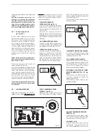
4.2.1
New fuel configuration
Access the parameters section by pres-
sing the control panel keys (
and
) at
the same time for 5 seconds. The red LED
flashes and the display shows :
Scroll the parameters using
or
.
To enter the fuel configuration paramater
PAR 01, use
or
.
The set value
flashes
a
MERIDIAN HE 30
C
on natural gas will be show as :
For a
MERIDIAN HE 30 C
boiler to func-
tion with LPG, press
until
05
appears
.
Confirm this value using
or
.
Exit the parameters section by pressing
.
The table below gives the values to set
when the supply gas is changed:
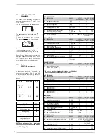
4.2.2
Calibrating the gas valve
pressures (See 4.8.1)
This can only be done using a flue gas analy-
ser. If the combustion reading is greater
than the acceptable value AND the integrity
of the complete flue system and combu-
stion seals have been verified, and the inlet
gas pressure has been verified then adjust-
ments to the gas valve can be made as
described below. Make only small adjust-
ments (1/8 turn max), and allow time for
the combustion analysis to be made before
making further adjustments.
Sequence of operations:
1)
Press buttons
and
at the same
time for 5 seconds. Chimney sweep mode,
see 4.5.1 (Lo) will appear on the display
and the boiler will work at minimum power.
2)
Press button
to raise the boiler to
maximum power (Hi).
3)
Determine the CO
2
values at max power
stated below, if required adjust using the
capacity step (5 fig. 16):
4)
Press button
to bring the boiler to
minimum power (Lo).
5)
Determine the CO
2
values at min power
stated below, if required adjust using the
OFF-SET adjustment screw (6 fig. 16):
6)
Press buttons
and
several times
to verify the pressures; if necessary,
make the appropriate corrections.
7)
Press button
to exit the function.
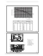
4.3
RATIO
Fig. 16
KEY
1
Upstream pressure intake
2
Intermediate pressure intake
3
Air signal inlet (VENT)
4
Downstream pressure intake
5
Capacity step
6
OFF-SET
4
USE, MAINTENANCE (including BENCHMARK) AND COMMISSIONIG
1
2
3
4
5
6
MAX power
Boiler
CO
2
CO
2
model
(Methane)
(Propane)
HE 30 C
9,0 ±0,3
10,0 ±0,3
MIN power
Boiler
CO
2
CO
2
model
(Methane)
(Propane)
HE 30 C
9,0 ±0,3
10,0 ±0,3
GAS MODELS
PAR 1
METHANE
(G20)
30 C
02
PROPANE
(G31)
30 C
05
CO ppm
100
400
0,0011
0,0044
0,0010
0,0040
1
2
3
3
Fig. 17


