background image

2686

7

GB

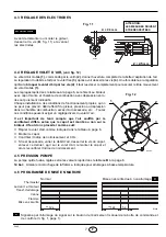
4.3 ELECTRODES SETTING

4.4 AIR DAMPER ADJUSTMENT,

 (see fig. 12)    

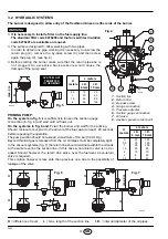
The mobile air damper (1) operated by the jack (2) assures the complete opening of the air intake.
The regulation of the air-rate is made by adjusting the fixed air damper (3), after loosing the screws (4). When
the optimal regulation is reached, screw tight the screws (4) to assure a free movement of the mobile air
damper (1)

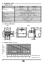
The settings, indicated in the table (page 6), refer to the burner with its
cover fitted and combustion chamber with depression zero.  These
regulations are purely indicative. 
Each installation however, has its own unpredictable working condi-
tions: actual nozzle output; positive or negative pressure in the com-
bustion-chamber, the need of excess air, etc. 
All these conditions may require a different air-damper setting.

It is important to take account of the fact that the air output of
the fan differs according to whether the burner has its cover
fitted or not.  
Therefore we recommended to proceed as follows:

  Adjust the air damper as indicated in the table.

  Mount the cover. 

Check smoke number and CO

2

.

  Should it become necessary to modify the air output, remove the

cover by loosening the screw, adjust the air damper, remount the
cover and finally recheck the smoke number.

4.5 PUMP PRESSURE:

The pump is set in factory according to the value indicated in the table B at page 6.

14 bar: Improves flame retention; it is therefore suitable for ignitions at low temperatures.

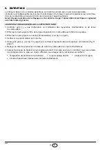
4.6 BURNER START-UP CYCLE

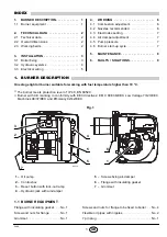
  Lock out is indicated by a lamp on the control box (3, fig. 1, page 1).


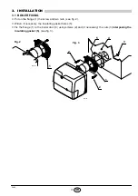
Before removing or assembling the
nozzle, loosen the screw (B, fig. 11)
and move the electrodes ahead.

ATTENTION

Fig. 11

 2.5

 mm

± 

0.3 mm

IMPORTANT:
THESE  DIMENSIONS
MUST BE OBSERVED

D5230

B

Fig. 12

4

3

D6286

4

1

2

Lock-out due to failure to light    


C

Normal

D5029

~

12s

Thermostat

Green led and motor

Ignition transformer

Oil valve

Flame

Lock-out lamp

~

12s

5 s

C

Summary of Contents for 8099020

Page 1: ...oudsvoorschriften Installation use and maintenance instructions Oil burners Br leurs fioul Stookoliebranders CODE MODEL MODELE TYPE 8099020 SIME MACK 4SP 515 T3 8099040 SIME MACK 5SP 515 T5 GB F NL On...

Page 2: ...4...

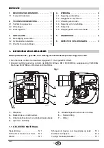
Page 3: ...INSTALLATION 3 3 1 Boiler fixing 3 3 2 Hydraulic systems 4 3 3 Electrical wiring 5 4 WORKING 6 4 1 Combustion adjustment 6 4 2 Nozzles recommended 6 4 3 Electrodes setting 7 4 4 Air damper adjustment...

Page 4: ...supply Single phase 50Hz 230V 10 Motor Run current 0 7A 2850 rpm 298 rad s Capacitor 4 F Ignition transformer Secondary 8 kV 16 mA Pump Pressure 7 15 bar Absorbed electrical power 0 13 kW Flange Burne...

Page 5: ...lange 1 the screw and two nuts see fig 2 Widen if necessary the insulating gasket holes 5 Fix the flange 1 to the boiler door 4 using screws 2 and if necessary the nuts 3 interposing the insulating ga...

Page 6: ...a non return valve is required This solution however is less safe than previous one due to the possibility of leakage of the valve It is necessary to install a filter on the fuel supply line The stan...

Page 7: ...he Country DO NOT EXCHANGE NEUTRAL WITH PHASE WARNING ACCESS TO THE PHOTORESISTANCE See fig 9 The photoresistance is fitted directly into the con trol box underneath the ignition transformer on a plug...

Page 8: ...efer to 12 5 CO2 at sea level and with light oil and room temperature of 20 C BOILER BURNER Nozzle Pump pressure Burner output Air damper adjustment Code Model GPH Angle bar kg h 4 Set point Rond Este...

Page 9: ...at the air output of the fan differs according to whether the burner has its cover fitted or not Therefore we recommended to proceed as follows Adjust the air damper as indicated in the table Mount th...

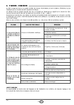
Page 10: ...s or dents in the supply or return oil pipes Clean the filter in the oil suction line and in the pump Clean the photoresistance see fig 9 page 5 Check for correct fuel consumption Replace the nozzle s...

Page 11: ...ied personnel FAULTS POSSIBLE CAUSES SOLUTION The green led on the control box is off and the burner does not start Lack of electrical supply Check presence of voltage in the L1 N clamps of the 7 pin...

Page 12: ......

Page 13: ...ion la chaudi re 3 3 2 Installations hydrauliques 4 3 3 Raccordements lectriques 5 4 FONCTIONNEMENT 6 4 1 R glage de la combustion 6 4 2 Gicleurs conseill s 6 4 3 R glage des lectrodes 7 4 4 R glage v...

Page 14: ...lectrique Monophas e 50Hz 230V 10 Moteur 0 7A absorb s 2850 t min 298 rad s Condensateur 4 F Transformateur d allumage Secondaire 8 kV 16 mA Pompe Pression 7 15 bar Puissance lectrique absorb e 0 13...

Page 15: ...vis et deux crous voir fig 2 Elargir si n cessaire les trous dans le joint isolant 5 Fixer sur la plaque de la chaudi re 4 la bride 1 par l interm diaire des vis 2 et si n cessaire des crous 3 en int...

Page 16: ...clapet de pied Dans le cas contraire le clapet de pied est indispensable Cette deuxi me solution est moins s re que la pr c dente en raison du man que d tanch it ventuel de ce clapet H m tres L m tre...

Page 17: ...directement sur la bo te de contr le au dessous du transformateur d allumage sur un support embrochage rapide Cellule photor sistance NOTES Section conducteurs 1 mm2 Les branchements lectriques ex cu...

Page 18: ...e CO2 au niveau de la mer avec une temp rature ambiante et du fioul de 20 C CHAUDIERE BRULEUR Gicleur Pression pompe D bit br leur R glage volet d air Code Mod le GPH Angle bar kg h 4 Index Rond Estel...

Page 19: ...uffl par le ventilateur diff re selon que le capot est mont ou non sur le br leur Il faut donc proc der comme suit R gler le volet d air comme indiqu dans le tableau page 6 Monter le capot Contr ler l...

Page 20: ...tour du combustible Effectuer le nettoyage du filtre de la ligne d aspiration du combustible et le filtre de la pompe Effectuer le nettoyage de la cellule photor sistance voir fig 9 page 5 V rifier si...

Page 21: ...e de contr le est teint et le br leur ne d marre pas Absence d alimentation lectrique V rifier la tension au bornier L1 N de la fiche 7 p les V rifier les fusibles V rifier que le thermostat ne soit p...

Page 22: ......

Page 23: ...etel 3 3 2 Hydraulische installatie 4 3 3 Elektrische aansluitingen 5 4 WERKING 6 4 1 Regeling verbranding 6 4 2 Aangewezen verstuivers 6 4 3 Afstelling electroden 7 4 4 Regeling van de luchtklep 7 4...

Page 24: ...s Elektrische voeding Monofasig 50Hz 230V 10 Motor Opgenomen stroom 0 7A 2850 t min 298 rad s Condensator 4 F Ontstekingstransformator Secundair 8 kV 16 mA Pomp Druk 7 15 bar Opgeslorpt vermogen 0 13...

Page 25: ...en in de flens 1 aanbrengen zie fig 2 Indien nodig de gaten in de flensdichting 5 vergroten Bevestig de flens 1 op de ketelplaat 4 met behulp van de schroeven 2 en indien nodig de moeren 3 en voeg de...

Page 26: ...voetklep noodzakelijk Deze tweede oplossing biedt echter minder zekerheid omdat de dichtheid van de voetklep eventueel ontoereikend kan zijn Het is noodzakelijk een filter te plaatsen op de voedingsli...

Page 27: ...gemonteerd onder de ontstekingstransfo op een houder met stekkerkoppeling Ontstekingstransfo Fotoweerstand E9102 NOOT Doorsnede geleiders 1 mm2 De elektrische aansluitingen die de installateur uitvoer...

Page 28: ...niveau en met temperatuur van de omgeving en van de stookolie op 20 C KETEL BRANDER Verstuiver Pompdruk Brander debiet Regeling luchtklep Code Model GPH Hoek bar kg h 4 Merkteken Rond Estelle 4 809902...

Page 29: ...dat de aangeblazen lucht van de ventilator verschilt naargelang de kap al dan niet gemonteerd is Men moet dus als volgt te werk gaan De luchtklep regelen zoals in de tabel blz 6 is aangegeven De kap m...

Page 30: ...er op de aanzuigleiding van brandstof en de filter van de pomp Reinig de fotoweerstand zie fig 9 blz 5 Kijk na of het brandstofverbruik normaal is Vervang de verstuiver zie fig 10 blz 6 en controleer...

Page 31: ...oos is uit en de brander ontsteekt niet Geen elektrische voeding Geen stroom Check de spanning aan het klemmen bord L1 N van de 7 polige mannelijke stekker Check de zekeringen Check of de thermostaat...

Page 32: ...Fonderie Sime S p A via Garbo 27 37045 Legnago Vr Italy Tel 39 0442 631111 Export Division fax number 39 0442 631293 Sime Service fax number 39 0442 631292...

Reviews: