NOTE:
If the plates are not neutralized, clean the emitters electrode and check its
performance again, following the procedure mentioned above. If
neutralization does not occur, please keep a record of the tests and contact
us or our agents in your area.
6.6 Ion Balance Check
6.6.1 Measure by charge plate monitor
To test the unit for ion balance, the use of a charge plate monitor is recommended.
Ion Balance (offset voltage) should be measured and checked against the specified
value given in section 2, Specifications. The specification in section 2 has been
prepared in accordance with ANSI/ESD STM3.1 ESD Association Standard Test
Method.
Do as a recommended measure condition as well as the measure of 6.5.1 ion output
check.
6.6.2 Measure excluding charge plate monitor
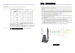
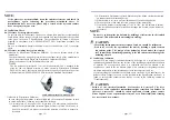
Measure by Electrostatic Fieldmeter FMX 003 for the ion balance check of the
①
-
attachment.
Can the measure by using the plate for the ion balance check of the attachment in
case of the measure with Simco-Ion Electrostatic Fieldmeter FMX-003.
(
)
Refer to the manual of the Fieldmeter about use etc.
NOTE
◇
The ion balance of Aerostat PC is
10V. Make within
20V a standard in the
±
±
plate for the ion balance measure of static electricity Electrostatic Fieldmeter
FMX-003 by relate, that an area and electrostatic capacity of the detection part are
different from ANSI/ESD STM3.1 ESD Association Standard Test Method.
Ion Balance measure with FMX-003
Measure by Electrostatic Fieldmeter
②
In case charged plate monitor is not available and a Electrostatic Fieldmeter in used
to check ion balance, following steps should be followed.
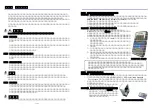
1) A metal plate, of size equal to or larger than 150 mm square, supported on
materials of high insulation resistance (glass, Teflon) is placed 30 cm away in
front of Aerostat PC air blower such that the direction of airflow is normal to
its surface.
-
-
page 12
2) A Electrostatic Fieldmeter is placed behind the plate. Make certain that ionized
air cannot reach the measuring device.
3) With the blower off, carry out zero adjustment of the measuring device.
4) Turn on the blower and read the static potential of the metal plate.
5) If a metallic board is electrification of -10V to +10V, the ion balance is normal.
If the electrification potential more than the range can be read, the ion balance is
not normal.
NOTE:
Do not try to determine ion balance by holding a static meter in the ionized
air stream. This will result in a meaningless reading.
CAUTION
- Measuring instruments used in sections 6.5 and 6.6 should be calibrated.
- Do not try to verify the operation of the unit by drawing a spark from an
ion emitter point. The design of the balancing circuit makes the “spark
test” inconclusive. Sustained grounding of the ion emitters may damage the
balancing circuit.
6.7 Ion Balance calibration
Aerostat PC's ion output is inherently balanced by design. As a result, there are no
calibration adjustments. Remove the surface of the insulating material where emitters
of Aerostat PC are supported when it is confirmed that the ion balance is not
excellent as a result of the ion balance check of 6.6 and remove the garbage such as
the dust which adhere to the insulation part with the compression air etc.
If, after checking the ion balance as outlined above (section 6.6), an unbalance or ion
balance (offset voltage) in excess of that specified in the Specification (section 2) is
found to exist, please contact Simco Japan's or refer to the following section on
"Troubleshooting".
CAUTION
Failure of the electrical insulation of electrodes in Aerostat PC by dirt,
moisture or other conductive contaminants might result bad ion balance. In
this case, Aerostat PC should be taken apart and cleaned, please contact
Simco Japan's or our representatives in your area. Disassembly and cleaning
are not covered by warranty.
-
-
page 13
Summary of Contents for Aerostat PC
Page 1: ...98070706 Simco Ion Ionizing Air Blower 1...
Page 2: ...Simco Ion Ionizing Air Blower 1 2 3 4 5 6 2 1 3...
Page 5: ...50cm 30 cm 100 V 50 60 Hz 8 50 Hz 9...
Page 7: ...FMX 003 ANSI ESD STM3 1 ESD Association Standard Test Method 150 30 12 a b c d 13...
Page 8: ...14 15...
Page 9: ...16 17...
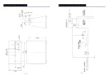
Page 19: ...Drawings AEROSTAT PC page 16 STAND DETAILS AEROSTAT PC SCHEMATIC page 17...

