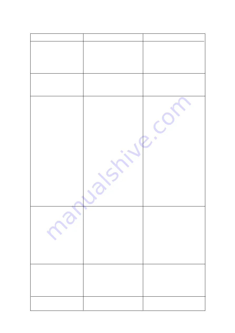
background image

Irregular cubes

Some jets plugged

Remove jet cover and clean

size & some cloudy

Shortage of water

See shortage of water

Unit not level

Level as required

Cubes too large

Freezing cycle too long

Adjust evap. thermostat

Inoperative evaporator thermostat

Replace thermostat

Decreased ice capacity

Inefficient compressor

Replace

Leaky water valve

Repair or replace

Non-condensable gas in system

Purge the system

Poor air circulation or excessive

Relocate the unit or provide for

hot location

more ventilation

(

Overcharge of refrigerant

Correct the charge. Purge off slowly

Capillary tube partially restricted

Blow charge, add new gas & drier,
after evacuating system with
vacuu pump

Hot gas solenoid valve leaking

Replace valve

Undercharge of refrigerant

Charge to data plate indication

Discharge head pressure too high

See incorrect discharge pressure

Poor harvest

Restriction in incoming water line

Check water valve strainer and flow
control. If necessary enlarge the
flow control orifice

Water inlet valve not opening

Valve coil with open winding
Replace valve

Hot gas valve orifice restricted

Replace hot gas valve assy

Discharge head pressure too low

See incorrect discharge pressure

Incorrect discharge pressure

Inoperative fan pressure control

Replace pressostat

Inoperative fan motor

Replace

Water regulating valve misadjusted Adjust its setting stem

Excessive water in unit base

Water tubing leaking

Check. Tighten or replace

SERVICE DIAGNOSIS

SYMPTOM

POSSIBLE CAUSE

SUGGESTED CORRECTION

Page 11

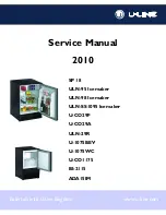
Summary of Contents for SDE-34-L

Page 1: ...SDE 30 SDE 34 SDE 40 SDE 50 SDE 64 SDE 84 SDE 170 SDE 220 Automatic cubers 090091 05 REV 11 2015 ...

Page 2: ...IEBSANLEITUNG 17 Starp up 4 Inbetriebnahme 17 Operational checks 4 Ueberprüfung im Betrieb 17 OPERATING PRINCIPLES 6 FUNKTIONSSYSTEME 19 Freezing Cycle 6 Gefrierprozess 19 Harvest Cycle 6 Abtauprozess 19 Control sequence 7 Steuersequenzen 20 Electrical sequence 7 Sequenz Elektrische Bestandteile 20 Components description 8 Komponentenbeschrieb 21 Service diagnosis 10 Fonktionsfehler 23 MAINTENANCE...

Page 3: ...ERATURE RAUMTEMPERATUR WATER COOLED MODELS WASSERKÜHLUNG WATER TEMPERATURE WASSERTEMPERATUR AMBIENT TEMPERATURE RAUMTEMPERATUR I CE PRODUCED PER 24 HRS EISWÜRFEL PRODUKTION IN 24 STD Kg C 10 21 32 38 27 21 15 32 10 46 45 44 43 42 41 40 39 38 37 36 35 34 33 32 31 30 29 AIR COOLED MODELS LUFTKÜHLUNG I CE PRODUCED PER 24 HRS EISWÜRFEL PRODUKTION IN 24 STD Kg C 10 21 32 38 27 21 15 32 10 AIR COOLED MO...

Page 4: ...164 162 160 158 156 154 152 150 148 146 144 142 140 138 136 134 132 130 128 126 Kg C 10 21 32 38 27 21 15 32 10 WATER COOLED MODELS WASSERKÜHLUNG AMBIENT TEMPERATURE RAUMTEMPERATUR AIR COOLED MODELS LUFTKÜHLUNG ICE PRODUCED PER 24 HRS EISWÜRFEL PRODUKTION IN 24 STD Kg C 10 21 32 38 27 21 15 32 10 WATER TEMPERATURE WASSERTEMPERATUR 215 213 211 209 207 205 203 201 199 197 195 193 191 189 187 185 183...

Page 5: ...SDE 30 ...

Page 6: ...SDE 34 ...

Page 7: ...SDE 40 ...

Page 8: ...SDE 50 ...

Page 9: ...SDE 64 ...

Page 10: ...SDE 84 ...

Page 11: ...SDE 170 ...

Page 12: ...SDE 220 ...

Page 13: ...Air Water Air Water Air Water Air Water Air Water Kühlung Luft Wasser Luft Wasser Luft Wasser Luft Wasser Luft Wasser Luft Wasser Luft Wasser Luft Wasser Bin Capacity kg Speiker Kapazität kg 6 5 10 12 17 20 30 50 68 Net weight kg Netto Gewicht kg 28 40 40 45 48 63 94 131 Compressor power HP Kompressorleistung PS 1 5 1 4 1 4 1 4 3 8 1 2 1 1 5 Running amps Ampere 1 9 2 2 2 2 2 1 3 1 3 8 5 3 5 5 Star...

Page 14: ...WIRING DIAGRAM SCHALTUNGSSCHEMA 230 50 1 AIR WATER COOLED LUFT UND WASSERGEKÜHLT SDE 30 34 40 50 64 84 ...

Page 15: ...WIRING DIAGRAM SCHALTUNGSSCHEMA 230 50 1 AIR WATER COOLED LUFT UND WASSERGEKÜHLT SDE 170 SDE 220 ...

Page 16: ...from the inside of the User Manual and fill in all parts including Model and Serial Number taken from the data plate Forward the completed self addressed registration card to SIMAG factory C LOCATION AND LEVELLING WARNING This Ice Maker is designed for indoorinstallation only Extended periods of operation at temperature exceeding the following limitations will constitute misuse under the terms of ...

Page 17: ...ly line with regular plumbing fitting and a shut off valve installed in an accessible position between the water supply line and the unit If water contains a high level of impurities it is advisable to consider the installation of an appropriate water filter or conditioner WATERSUPPLY WATER COOLED MODELS SDE 84 170 220 The water cooled versions of SIMAG Ice Makers require two separate inlet water ...

Page 18: ...to the factory 12 Has the owner been given the name and the phone number of the authorized SIMAG Service Agency serving him F FINAL CHECK LIST 1 Is the unit in a room where ambient temperatures are within a minimum of 10 C 50 F even in winter months 2 Is there at least a 15 cm 6 clearance around the unit for proper air circulation 3 Is the unit level IMPORTANT 4 Have all the electrical and plumbin...

Page 19: ...with the start up of Fig 1 COMPRESSOR CONTACTOR COIL SDN85 145 215 WATER PUMP FAN MOTOR in air cooled version D Check to see through the ice discharge opening that the spray system is correctly seated and that the water jets uniformely reach the interior of the inverted mold cups or the exterior of the evaporator tips also make sure that the plastic curtain is hanging freely and there is not exces...

Page 20: ...he harvest cycle hold ice against the bin thermostat control bulb to test its shut off This should cause the ice maker to shut OFF after 30 seconds 1 minute at the most namely when the control bulb temperature drops to reach 1 C NOTE In case this test is performed during the freezing cycle the unit will shut OFF only at the end of the freezing cycle Within minutes after the ice is removed from the...

Page 21: ...and SDE220 air cooledthe refrigerant head pressure in the course of the freezing cycle ranges between 8 10 bars SDE64 8 9 5 bars SDE84 and 15 5 20 bars SDE170 220 being controlled by the hi pressure control When the discharge pressure rises up to a pre setvalue the pressure control closes its electrical contacts suppling power to the FAN MOTOR As soon as the discharged refrigerant pressure drops t...

Page 22: ... the evaporatorthermostat can be made by turning its adjusting screw located on front side With a clockwise rotation of the setting screw the thermostat cut IN temperature will be lowered longer freezing cycle thicker ice cube while with a counterclockwise rotation of the screw the Cut IN temperature rises shorter freezing cycle thiner ice cube Once completed the freezing cycle 2nd phase thesystem...

Page 23: ...er filling cycle D TIMER Equippedwith two DIP switch and a Potentiometer it is located inside the control box The function of the timer begins when activated by the cube size control evap thermostat The large diameter lobe of its cam determines the 2nd freezing cycle portion length while the cam sall diameter lobe determines the time cycle for the harvest sequence Potentiometer used to adjust the ...

Page 24: ...igerant liquid line and electrically connected upstream all other controls this safety device shut off the icemakers when senses that the temperature at the liquid line has rised to the limit of 75 C 170 F or corresponding pressure H WATER SPRAY SYSTEM It consists of one spray bar with several spray nozzles on its extension Thewater pumped is sprayed through its nozzles in each individual mold or ...

Page 25: ...gh room temperature Move the unit in a more suitable place Cubes too small Freezing cycle too short Review setting of DIP SWITCH keys Capillary tube partially restricted Blow charge add new gas drier after evacuating system with vacuum pump Moisture in the system Same as above Shortage of water See remedies for shortage of water Shortage of refrigerant Check for leaks recharge Inoperative evaporat...

Page 26: ...g system with vacuu pump Hot gas solenoid valve leaking Replace valve Undercharge of refrigerant Charge to data plate indication Discharge head pressure too high See incorrect discharge pressure Poor harvest Restriction in incoming water line Check water valve strainer and flow control If necessary enlarge the flow control orifice Water inlet valve not opening Valve coil with open winding Replace ...

Page 27: ...wn bin drain line to be sure that drain line is open and clear 6 Check size condition and texture of ice cubes Perform adjustment of the evaporator thermostat or cube size control by turning its adjusting screw clockwise for a thicker ice cube and counterclockwise for a thiner one 7 Check the bin thermostat to test shut off Put a handfull of ice cubes in contact with its bulb This should cause the...

Page 28: ...uring on them some warm water This to prevent somebody from using them 15 Wipe clean and rinse the inner surfaces of the storage bin REMEMBER To prevent the accumulation of undesirable bacteria it is necessary to sanitize the interior of the storage bin with an anti algae disinfectant solution every week Page 13 2 Wait till the end of defrost cycle then shut the unit OFF by means of its master swi...

Page 29: ...et com sg I C E M A C H I N E S Certified ISO 9001 TOTAL QUALITY SIMAG via Risorgimento 4 20017 Mazzo di Rho MI Italy Tel 39 02 93900215 Commerciale Sales Dept Tel 39 02 93960357 Assistenza Service Dept Fax 39 02 93900226 Commerciale Sales Dept Fax 39 02 93960366 Assistenza Service Dept e mail sales simag it e mail service simag it www simag it ...

Reviews: