background image

6

CONNECTING THE TWO UNITS

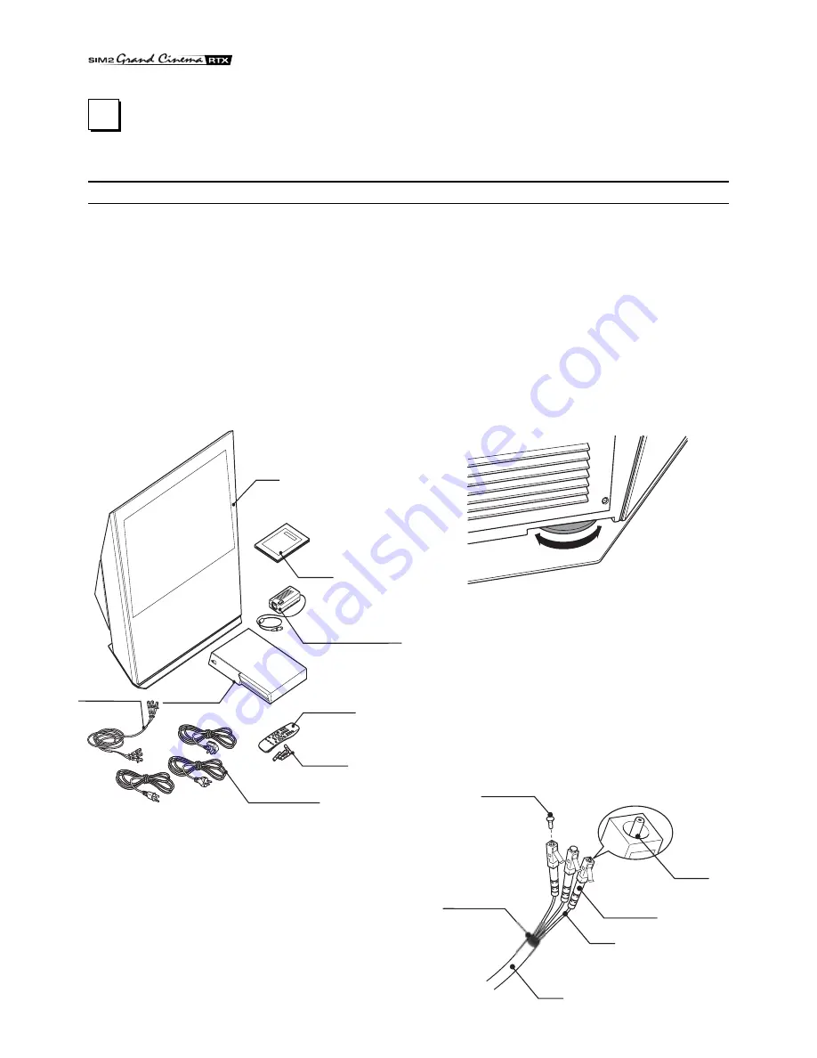
The RTX system consists of two separate units (the DigiOptical
Image Processor and the Display), each of which is equipped
with a power cable; the two units are interconnected by a 20 m
fibre optic cable.

The ideal location for the DigiOptical Image Processor is on a
cabinet shelf or on a rack (dimensions compatible with a standard
19" rack). Make sure that the support surface is stable and that
the unit has sufficient space around it for ventilation purposes
(at least 3 cm).
The unit is connected to the mains via an external power supply
unit with an output of +7 Vdc; the unit’s main power switch is on
the power supply unit.

Display

Alimentatore
DigiOptical
Image Processor

Remote Control

1.5 V AAA- 
type batteries

Power cables  
Europe, UK, US (x2)

DigiOptical
Image Processor

Three-core 
fibre optic cable  

Instruction  
Manual

D

I G

I O

P

T

I C

A

L  

I M

A

G

E

  P

R

O

C

E

S

S

O

R

O

I

DigiOptical Image 
Processor power supply unit

1    INSTALLATION

SIM2’s RTX system is made up of the following components
(Fig.1):

Display

DigiOptical Image Processor

remote control

DigiOptical Image Processor power supply unit

three power cables for the Display

three power cables for the DigiOptical Image Processor

triple fibre optic cable for linking the
DigiOptical Image Processor and the Display

four 1.5 V AAA-type batteries for the remote control

User and installation manual

If any accessories are missing, contact your Dealer as soon as
possible.

Connect the power supply unit output cable to the POWER
socket located on the rear panel (Fig. 4).
Use exclusively the power supply unit provided with the system
or an alternative power supply unit expressly approved by SIM2.

The Display is designed to stand on the floor. Place the Display
on a flat, level surface where it has sufficient space for ventilation;
to prevent glare and reflections, avoid places exposed to direct
sunlight or intense light sources.
The mains power input socket and the power switch are both
located on the rear panel.
Adjust the rear feet to obtain the optimum viewing angle in
accordance with the distance and height of the viewing position
in front of the Display (Fig. 2).
The system can be fully controlled using the supplied IR

Fig. 1

(infrared) remote control handset. There is a single remote control
for both the DigiOptical Image Processor and the Display; the
remote control can be directed towards either unit since they
are both equipped with an IR sensor.

The connection between the two units is made with a single
cable containing three fibre optic cables each terminating in an
LC connector. The standard cable length of 20 m will be sufficient
for most installation requirements.

Fig. 2

Cavo

Fibra

Ferrule

Connettore

Tappo di 
protezione

Punto di 
sfiocco

Protective cap

Separation point

Cable

Connector

Fibre

Fig. 3

Summary of Contents for RTX 45

Page 1: ...USER AND INSTALLATION MANUAL ENGLISH RTX 45 55...

Page 2: ...operating at high temperatures Do not remove the cover from the units refer to qualified service personnel for all repair and maintenance requirements The warranty will be automatically invalidated i...

Page 3: ...l 9 Fibre optic link 9 2 OPERATION 10 SWITCHING ON AND OFF 10 KEYPAD 11 REMOTE CONTROL 11 ON SCREEN MENUS 12 Inputs 12 Main Menu 13 Picture 13 Image 14 Setup 15 Info 15 Quick Menus 15 Messages 15 MAIN...

Page 4: ...of the SIM2 Grand Cinema RTX system The RTX system combines the signal processing capabilities of the DigiOptical Image Processor with the high fidelity reproduction of the DLP technology Display by...

Page 5: ...or reduction of image sharpness thanks to the processor s high pixel rate signal acquisition capabilities Adaptation of the input signal resolution to the Display resolution occurs without alteration...

Page 6: ...ur 1 5 V AAA type batteries for the remote control User and installation manual If any accessories are missing contact your Dealer as soon as possible Connect the power supply unit output cable to the...

Page 7: ...NC connectors 8 Each set of connectors is suitable for RGB and Component signals RGB signals can have the following synchronisations composite sync on the green signal RGsB H V Composite Sync or se pa...

Page 8: ...aphics RGB DVI D 11 Table 2 Fig 4 DC IN 12V OUT VID EO S VID EO COMPONENT RGBS COMPONENT RGBS R Cr V G Y B Cb H HV R Cr V G Y B Cb H HV R Cr V G Y B Cb H HV R Cr V G Y B Cb H HV GRAPHIC S RGB DVI D 1...

Page 9: ...sing a cable with a DB15HD type connector The signal source device typically a personal computer or game console must be able to provide separate H V synchronisation or composite H V synchronisation o...

Page 10: ...Initialisation Status DigiOptical Image Processor Display Green LED Blue LED Front LED Keyboardpad Stand by On Cooling Optical link not active Caution Error Off On Flashing Insignificant ESC MENU AUTO...

Page 11: ...nfrared signals There are two infrared sensors one at the front of the Display and one on the front panel of the DigiOptical Image Processor Avoid placing obstructions between the remote control and t...

Page 12: ...ptimisation of the displayed image Not active in this model ON SCREEN MENU All system functions can be activated from the keypad or remo te control with the aid of a practical and comprehensive system...

Page 13: ...ade with the keys Fig 14 These submenus are accessed by pressing the key while exit and return to the upper level occurs by pressing MENU Press ESC on the remote control or keypad to interrupt the men...

Page 14: ...e 16 9 screen of the Display PIXEL TO PIXEL This aspect displays the image as it is input without adapting it to the screen The image is projected in the centre of the screen and if its horizontal and...

Page 15: ...stments or keys 1 9 on the remote control to select one of 9 preset positions Position Aspect Video S Video RGBS 32 kHz YCrCb 32 kHz RGB Grafico DVI D RGBS 15kHz YCrCb 15kHz Adjustments Inputs Frequen...

Page 16: ...d the Display Picture is disturbed unstable or noisy Check compatibility of the video or graphic signals with the technical specifications of the system and specifically with the specifications of the...

Page 17: ...IMAGE menu to reduce colour misalignment Remote control not working Check remote control battery power and correct polarity Ensure the area between the infrared sensors on the front panel of the Digi...

Page 18: ...68 2 31 IEC 68 2 32 ELECTRICAL Input signals 2 COMPOSITE VIDEO CVBS RCA type connectors gold plated 1 0 Vpp 75 negative synchronisation 2 S VIDEO Y C 4 pin mini DIN connectors Y 1 0 Vpp 75 negative sy...

Page 19: ...nsions 483 x 55 x 200 mm WxHxD compatible with 19 rack Weight approx 2 5 kg Operating Temperature 10 to 35 C Transportation temperature 15 to 55 C Storage temperature 15 to 55 C Humidity 20 to 95 non...

Page 20: ...65 1188 mm 46 78 235 mm 9 25 368 6 mm 14 51 1108 mm 43 62 1108 mm 43 62 245 mm 9 64 420 3 mm 16 54 1218 mm 47 95 560 5 mm 22 07 1218 mm 47 95 684 9 mm 26 96 RTX 45 RTX 55 DIMENSIONS DISPLAY DIGIOPTIC...

Page 21: ...ed Green Blue Brightness Contrast Sharpness Sharpness Mode Brightness Contrast Colour Tint Sharpness Sharpness Mode 32kHz Brightness Contrast Colour Sharpness Filter Cinema Mode Video Type Video S Vid...

Reviews: