background image

��

33

1   INTRODUCTION 

2    IMPORTANT SAFETY INSTRUCTIONS 

5

3     UNPACKING 

9


Pack contents  

10

4     INSTALLATION 

11


Positioning the unit 

11


Connecting the video sources 

13

5     SWITCHING ON AND OFF 

15


Switching on/off from stand-by 

15

6    KEYPAD   

17

7   REMOTE CONTROL 

17

8    ON-SCREEN MENU 

18


Inputs   

18


Main menu 

18


Picture  

19


Image   

20


Set up   

22


Menu   

22


Memories 

24


Info 


25


Quick menus 

25


Messages 

25

 9    CLEANING AND MAINTENANCE 

26

10   TROUBLESHOOTING GUIDE 

26 

11  OPTIONAL ACCESSORIES 

27

12  ADDITIONAL INFORMATION 

28


a technical specifications 

28


b dimensions 

29


C on-screen menus layout 

30

SUMMARY

Summary of Contents for Grand Cinema HTL40 LINK

Page 1: ...cod 46 0452 000 Manual and installation guide HTL40 ...

Page 2: ... pages FREEZE Freezes unfreezes the picture F1 Programmable function key F2 Programmable function key ASPECT Selects picture aspect ratio VCR Activates a filter to improve video recorder signal quality INFO Displays selected source information and system status MEMORIES Activates the Memories management menu MENU ActivatestheOnScreenDisplaymenusandallows navigation though the various pages Up Down...

Page 3: ... 3 1 INTRODUCTION Congratulations on your choice of the innovative SIM2 GrandCinema HTL40 system ...

Page 4: ...as sure optimum reproduction of all the different input signals from interlaced video to high definition video and graphics The images generated are always sharp detailed and with natural colours The large number of inputs available 1 Composite Video input 1 S Video input up to 2 Component or RGB inputs 1 graphic RGB input 1 DVI D input and 1 HDMI input ensures the system sup ports a wide variety ...

Page 5: ...TIONS This symbol indicates the presence of impor tant instructions regarding use and mainte nance of the product Read all chapters of this manual carefully before switching on the screen This manual provides basic instructions for using the HTL40 system Installation preliminary adjustments and procedures that necessitate opening the units and touching electrical components must be carried out by ...

Page 6: ... 6 1 Fused power socket 2 Bushes 3 Keypad 4 Curved rear panel 5 Screen 6 Main power switch PARTS LIST ...

Page 7: ...he mains power supply The fuse compartment is next to the mains power connector Fig 2 Remove fuse carrier 2 with the aid of a flat blade screwdriver then change fuse 3 Insert a new spare fuse 4 Use only T5A H fuses Fig 2 Beware of power supply cables Position the cables carefully to avoid a trip hazard and make sure they are kept out of reach of children Install the unit as close as possible to th...

Page 8: ...t for fixed ceiling or wall installation Never use the screen by resting it on either of its sides or on the rear panel Do not insert objects through the units openings Make sure that no objects are inserted inside the unit If this should occur disconnect the unit from the power supply immediately and call an authorised technician ...

Page 9: ...KING To remove the HTL40 system from its carton follow the figures on the left Fig 3 The carton and packaging should be retained for future use and in the unlikely event that your system needs to be returned for repair ...

Page 10: ...for remote control three power cables EU UK USA for the screen one HDMI HDMI cable one HDMI DVI cable user manual If any accessories are missing contact your Dealer as soon as possible HDMI TM HDMI TM cable Curved rear panel Instruction manual Remote control 1 5 V AAA batteries Power cables Europe UK US Screen HDMI cable TM DVI ...

Page 11: ...people Sim2 Multimedia declines all liability for possible injury to persons or damage to prop erty deriving from incorrect installation of the screen Make sure the components listed below are within easy reach TFT LCD flat screen curved rear panel the fixing screws spacers for installation with VESA interface With the panel supported in a vertical position insert the mains power cable connector i...

Page 12: ...he power cable plug into the socket on the LCD panel Fig 5 Caution Do not supply power to the panel by plugging the power cable into the mains socket outlet until you have finished the installation procedure Position the curved rear panel at the back of the display and line up the four holes with the bushes Fig 8A fixing the parts together with the flathead screws Fig 8B Fig 8 CONTROL OF THE SYSTE...

Page 13: ...eature several outputs To obtain the best performance from your system carefully choose which output to use Generally the type of signal offering the best picture quality is DVI D followed by RGB Components S Video and Composite Video in that order However the HTL40 system is equipped with an excellent Video Decoder and Deinterlacer and therefore even lower quality signals will produce high qualit...

Page 14: ...ally the corresponding output on the source can be identified by the wording S VIDEO or Y C The S VIDEO signal output is available on numerous video sources DVD players video recorders video cameras still cameras etc This signal is preferable to Composite Video because it gives better picture quality RGB YCrCb The RGB YCrCb inputs are composed of two groups of four RCA con nectors each The two set...

Page 15: ...e the operating status of the system in accordance with the contents of Table 2 Unit HTL40 can be controlled either from the remote control or from the keypad located on the top of the screen Table 2 SWITCHING ON AND OFF FROM STAND BY Switching on the system Fig 11 from the remote control keys 0 9 from the screen keypad keys and Typically the picture will appear after 15 20 seconds R C I 2 0 0 5 L...

Page 16: ...R C I 2 0 0 5 L IG H T A U T O Fig 11 To allow the unit to cool down do not set the mains power switch to the O position or unplug the power supply cable immediately after having set the system to stand by mode We recommend waiting for several minutes before switching off the unit completely ...

Page 17: ...ansmitting commands to the system Remove batteries from the remote control if it is to remain unused for a long period of time to avoid the risk of potentially harmful chemical leaks Dispose of spent batteries at specific battery collection points 6 KEYPAD The keypad on the top of the screen features eight keys providing the facility for complete control of the unit even without the remote control...

Page 18: ...ll inputs after pressing the key Once the input has been selected a brief phase starts during which the system analyses the applied signal while a message is displayed showing the requested signal As soon as the system locks on to the signal the picture is displayed and a window appears containing information relative to the specific video format and standard for video signals or the resolution fo...

Page 19: ... images will be shown in black and white Increasing the value try to find the point at which the colours look natural suitable references include skin tones and grass in landscape shots TINT Controls the purity of the colours Basically determines the red green ratio of the picture Reducing the value will boost the red contents of the picture increas ing the value will boost the green tones For thi...

Page 20: ...affected by the filter while the filter is active on the right hand side this makes it possible to compare the changes resulting from noise filtration with a clean unfiltered image It is possible to deactivate the filter NOT ACTIVE using the automatic AUTO setting or manually MANUAL selecting the most suitable value for the picture with the VALUE adjustment In this latter case it is sufficient to ...

Page 21: ...n darker parts of the picture although the global perception of contrast is reduced Values higher than 2 2 increase the global perception of contrast while attenuating the visibility of details in darker areas of the picture With the most common video sources a parameter value of 2 2 will give high quality pictures with the right amount of contrast OVERSCAN Eliminates irregularities around the out...

Page 22: ...ction TEXT INSERT Characters are entered using a specific text input menu Fig 18 This menu provides the facility to store text strings easily and quickly Y C DELAY In the case of Video and S Video signals it may be necessary to correct horizontal colour misalignment within the projected image For a given video standard e g PAL or NTSC the stored value does not normally require further fine tuning ...

Page 23: ...e represented by the table columns Choose the required column using the and keys on the remote control this will enable you to identify one of the two keys F1 or F2 now select the function to assign to the key F1 or F2 by means of the and keys on the remote control The function performed by the key is confirmed by the appearance of a dot on the corresponding column row intersection The functions a...

Page 24: ... IMAGE PICTURE BRIGHTNESS ASPECT CONTRAST COLOUR TEMPERATURE COLOUR OVERSCAN TINT GAMMA SHARPNESS FILTER SHARPNESS MODE VIDEO TYPE NOISE REDUCTION Some of these parameters may not be available for certain inputs or certain input signals in accordance with the definitions in Tables 3 and 4 Pressing the key on the remote control or the key on the keypad Fig 20 serves to activate the menus management...

Page 25: ...ected in the penultimate access to the Memories page Memory 0 can be used even when you do not wish to enable Memories management for the signal in use Once selected each time a source is chosen the system will automatically reload the settings that were active the last time the source was used INFO Displays information concerning the displayed video graphic signal and the operating status of the ...

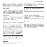
Page 26: ...aphic signals supplied by the source are compatible with the system s technical specifications and in particular with those of the selected input Check the condition of the cables used to connect the HTL40 panel to the various sources If the problem occurs on a terrestrial broadcast source signal check that the receiver has been correctly tuned in and that the aerial system is in good working orde...

Page 27: ...TO key on the screen keypad to execute automatic adjustments Adjust Frequency and Phase parameters in the IMAGE menu to optimise the vertical detail of the displayed image Video image showing colour misalignment on vertical details Make sure the video or graphic signals supplied by the source are compatible with the system s technical specifications and in particular with those of the selected inp...

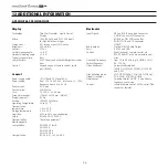
Page 28: ...erature 15 to 55 C Humidity 20 to 95 non condensing Safety EN 60950 UL 60950 Transportability desktop equipment Electromagnetic compatibility EN 55022 Class B EN 55024 EN 61000 3 2 EN 61000 3 3 Transportation IEC 68 2 31 IEC 68 2 32 A TECHNICAL SPECIFICATIONS Electronics Input Signals VBS on RCA Phono type connector S VIDEO on mini DIN connector RGBHV on DB15HD connector RGBS YCrCb on RCA connecto...

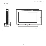
Page 29: ... 29 B DIMENSIONS Screen Unit of measure mm ...

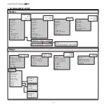
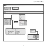
Page 30: ... 30 C ON SCREEN MENU LAYOUT HDMI Video S Video YCrCb RGB Graphic RGB YCrCb 15kHz RGBS 15kHz ...

Page 31: ... 31 ...

Page 32: ... 32 ...

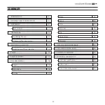
Page 33: ...witching on off from stand by 15 6 KEYPAD 17 7 REMOTE CONTROL 17 8 ON SCREEN MENU 18 Inputs 18 Main menu 18 Picture 19 Image 20 Set up 22 Menu 22 Memories 24 Info 25 Quick menus 25 Messages 25 9 CLEANING AND MAINTENANCE 26 10 TROUBLESHOOTING GUIDE 26 11 OPTIONAL ACCESSORIES 27 12 ADDITIONAL INFORMATION 28 a technical specifications 28 b dimensions 29 C on screen menus layout 30 SUMMARY ...
Page 34: ...434 383260 261 www sim2 com e mail info sim2 it SIM2 USA Inc 10108 USA Today Way 33025 Miramar FL USA Phone 1 954 4422999 Fax 1 954 4422998 www sim2usa com e mail sales sim2usa com SIM2 Deutschland GmbH Gewerbepark 17 D 35606 Solms Phone 0800 800 7462 Fax 0800 900 7462 www sim2 com e mail info de sim2 it SIM2 UK LTD Steinway House Worth Farm Little Horsted Nr Uckfield East Sussex TN22 5TT Phone 44...

Reviews: