background image

16

ht5000

MAiN MENU

To  access  the  main  menu  of  the  On  Screen  Display  press 

the MENU key on the keypad or the MENU+ or MENU- key on the 

remote control. 

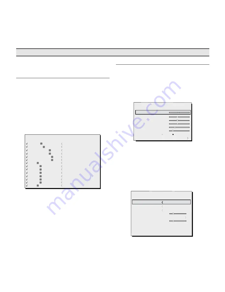
The  main  menu  is  divided  into  four  windows,  PICTURE, IMAGE, 

SETUP and MENU, in which the various adjustments are grouped 
according to the frequency of use. Use the 

 and 

 keys to 

select  the  line  corresponding  to the  adjustment  you  wish  to 

make (Fig. 15). 

The various menus only offer the relevant adjustments in ac-

cordance with the type of input signal displayed (e.g. certain 

typical adjustments for video signals, not necessary for graphic 

signals, do not appear on the menus, and vice versa). 

Some adjustments (e.g. BRIGHTNESS and CONTRAST) are associated 

with a numerical value that can be varied within the set limits 

using the 

◀ 

and 

 keys. 

For  others  (e.g.  CINEMA MODE)  you  can  choose  between  two 

options presented on the same line and selectable using the 

keys 

◀ 

and 

 (Fig.16a/b).

.


Picture

Contrast 

Color

Tint 

Sharpness 

Filter 

Cinema Mode 

50 

50 

50 

Off 

Auto 

Auto

Noise Reduction

Brightness 

60 

iNPUTS

The input selection menu is called by pressing 0 on the remote 
control or with the keypad SOURCE key. To select an input, scroll 
through the list with the 

 e 

 keys until the required input is 

highlighted, then press 

.

Display of the input selection menu is terminated by pressing 
the ESC key or when the On-Screen Menu display timeout in-
terval (set in the Menu Setup) has elapsed or after the signal's 
recognising.
The inputs can receive RGB and YPrPb signals, at 15 kHz,  kHz 
or higher. The input and type of signal (RGB or YPrPB) are set in 
the pull down menu at the right of the symbol < after pressing 
the 

◀ 

key (Fig. 14). 

2  S-VIDEO 

5  GRAPHICS RGB

3  COMPONENT 

1  VIDEO

1

2

3

5

S-VIDEO

GRAPHICS

COMPONENT

VIDEO

4  COMPONENT 

4

COMPONENT

6  GRAPHICS RGB

6

GRAPHICS

7  DVI

7

DVI

Source list / Rename source  


9  HDMI 

12  HDMI 

10  HDMI 

8  HDMI

8
9

10

12

HDMI 

HDMI

HDMI

HDMI

11  HDMI 

11

HDMI

13  HDMI 

13

HDMI

14  SDI

14

SDI

HDMI 8-1 inputs can receive the signals from DVI-D sources. 
During the short time it takes to find the signal, a box appears 
showing the signal requested. As soon as the signal is shown  
additional information is displayed in the box concerning the 
video  standard  (for  video  signals)  or  resolution  (for  graphic 
signals), format and the eventual user's memory.
This information can be recalled  by pressing the numerical key 
that it corresponds at the selected source.
In the SETUP  menu you can select whether to display this infor-
mation or not; for further information  see SOURCE INFORMATION  in 
the MENU  menu.

Fig.14

8  ON SCREEN MENU

All  system  functions  can  be  operated  from  the  keypad  or 
remote control, with the aid of a complete, user-friendly on 
screen menu. 

Fig.15

Color   Temperature 

Gamma Correction 

Position 

Y/C Delay 

Overscan 

Aspect 

Image

Fig.16a

Summary of Contents for GRAND CINEMA HT HT5000

Page 1: ...usaer and installation manual HT5000 USER aND INSTaLLaTION MaNUAL 460604000...

Page 2: ...p Down call up the quick menus MENU Switches on the On Screen Display and navigates between its pages MEMORIES Activates the Memories management menu INFO Displays information about the selected sourc...

Page 3: ...t 1 S Video input 2 Components or RGB input 4 RCA 5 BNC 2 Graphic RGB input 6 HDMI inputs 1 HD SDI input 1 DVI D input allow it to be connected to a wide range of analogue and digital sources DVD play...

Page 4: ...to promote the use of natural materials SIM2 Multimedia provides the following information regarding the disposal and recyclig of the product Electrical and electronic waste materials WEE should never...

Page 5: ...is equipment does cause harmful interference to radio or television reception which can be determined by turning the equipment off and on the user is encouraged to try to correct the interference by o...

Page 6: ...plug not the cable to disconnect the unit from the mains 1 Projection lens 2 Magnetic cover for lens sostitution 3 Remote control IR sensor on front of unit 4 Unblock lens hole 5 Adjustable feet 6 Coo...

Page 7: ...d placing it in poorly ventilated areas as this can lead to overheating Never look directly at the projection lamp Never look directly into the lamp when it is on as the inten se light can damage your...

Page 8: ...emote control four 1 5V AAA batteries for remote control three power cables EU UK USA for the projector the user manual If anything is missing immediately inform your dealer Remote Control 4 1 5V AAA...

Page 9: ...stance from the screen the size of the projected image is a function of the distance between the lens and the screen and the lens zoom setting Use the motor zoom Fig 3 to zoom the projected image in a...

Page 10: ...the projected image aspect ratio changes Fig 7 This option is controlled via the output TRIG2 at the rear of the projector TRIG 1 TRIG 2 For rear projection the screen must be translucent For front pr...

Page 11: ...switched on from standby the lamp switches on after a brief period of warming up the image displays blue led on The projected image comes from the input selected when the unit was last switched off Fi...

Page 12: ...ance For optimum connectivity we recommend you follow these simple steps With exception of coaxial RCA Phono type connectors always double check that the plug is inserted the correct way round to avoi...

Page 13: ...er HDTV Receiver DVD Player Videorecorder Game Console Television receiver HDTV Receiver DVD Player Videorecorder Game Console HDTV Player Blue Ray Player Computer 6 14 Professional broadcasting equip...

Page 14: ...normally coloured yellow and will often be labelled VIDEO Other signal and socket formats may be preferable because they give better image quality but this type of output socket is still the most comm...

Page 15: ...ped with two outputs Voltage 12V for motorised projection screen and screen masking systems used for masking off the projection area to match the projected image aspect ratio Fig 12 The TRIG1 output i...

Page 16: ...inated by pressing the ESC key or when the On Screen Menu display timeout in terval set in the Menu Setup has elapsed or after the signal s recognising The inputs can receive RGB and YPrPb signals at...

Page 17: ...hting and try to ensure that all the objects remain separately identifiable COLOR This control also called Saturation increases or decreases the picture colour intensity When set to zero colour images...

Page 18: ...c is ideal for displaying a 4 3 image on the 16 9 screen of the Display SUBTITLES raises the image thus making space for subtitles Pixel to Pixel runs a pixel to pixel mapping of any image without ada...

Page 19: ...aying graphic images in mode rate controlled light USER With USER curve the the user may select the exponent gamma value used for gamma compensation Table 5 Gamma correction settings Gamma functions S...

Page 20: ...n this procedure is called it is helpful to have a white or light coloured background on the screen in the current picture Y C Delay In the case of Video and S Video signals it may be necessary to cor...

Page 21: ...hould allow the viewer to distinguish each pixel that create the image one from another In the initial phase of installation the configurable keys F1 F2 serve as optical zoom and optical focus LAMP PO...

Page 22: ...select NAME and rename the source This makes it easier to remember which source is connected to a given input you can use up to 12 alphanumeric characters for the name for further details see Enterin...

Page 23: ...ions Color Temperature Successive pressing F1 or F2 key makes it possible to select among the available color temperature setting Gamma Correction Successive pressing F1 or F2 key makes it possible to...

Page 24: ...e relative to the Memory in question and open the corresponding drop down menu key Select the line Save initial settings To confirm the operation the message Initial settings saved in Memory 1 is show...

Page 25: ...on your screen No Signal The system does not recognise any signal applied to the se lected input In this case Make sure the selected input is connected to a video or graphic signal and that that sourc...

Page 26: ...ources Check the state of the connection by interpreting the code displayed by the system LEDs Make sure the cooling air vents on the units are not blocked and that the ambient temperature is below 35...

Page 27: ...to the image on the IMAGE OVERSCAN menu Image too dark too pale or unnaturally coloured Check compatibility of the video or graphic signals with the technical specifications of the system and specific...

Page 28: ...automation devices USB 1 1 LAN RJ45 Horizontal frequency from 15 to 80 kHz up to to UXGA format 65 Hz Vertical frequency 48 100 Hz Video Standard automatic selection PAL B G H I M N 60 SECAM NTSC 3 5...

Page 29: ...rightness Contrast Color Sharpness Sharpness Mode Noise reduction Aspect Color Temperature Gamma Correction Aspect Color Temperature Gamma Correction Overscan Position Y C Delay Aspect Color Temperatu...

Page 30: ...e name 1 ABC 2 DEF 3 GHI 4 JKL 5 MNO 6 PQRS 7 TUV 8 0 WXYZ 9 _ _ _ _ _ _ _ _ _ _ _ Cancel Confirm Edit memory name 1 ABC 2 DEF 3 GHI 4 JKL 5 MNO 6 PQRS 7 TUV 8 0 WXYZ 9 _ _ _ _ _ _ _ _ _ _ _ Save curr...

Page 31: ...31 ht5000 DIMENSION 1 Unit mm...

Page 32: ...32 ht5000 DIMENSION 2 VALID MEASUREMENT ONLY WITH STANDARD LENS...

Page 33: ...18 8 24 0 25 2 34 6 34 6 45 0 56 2 80 0 Throw Distance Throw FWA Fixed Wide Angle Throw Distance Image Width Lens Type FWA 1 FWA 2 Short Med short Med long Long Throw Ratio 0 67 1 1 12 1 1 39 1 87 1 1...

Page 34: ...0 70 H Screen Height 1H 30 H Center 0 30 W Screen Width 1W 30 W VERTICAL SHIFT UP 30 of image height 70 of image height DOWN HORIZONTAL SHIFT LEFT 30 of image width 30 of image width RIGHT VERTICAL H...

Page 35: ...ww sim2 com e mail info sim2 it SIM2 USA Inc 10108 USA Today Way 33025 Miramar FL USA Phone 1 954 4422999 Fax 1 954 4422998 www sim2usa com e mail sales sim2usa com SIM2 Deutschland GmbH Frankfurt am...

Reviews: