Smart Machine Smart Decision
SIM868_Series_Hardware_Design_V1.06
52
2017-07-13
6.8.2.
Active Antenna
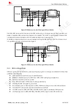
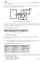
Active antenna has an integrated Low-Noise Amplifier (LNA). VCC_ANT is needed on customer’s application
board for the active antenna power input, as shown in Figure 50.
C101
MODULE
GPS_ANT
GND
C102
R101
Matching circuit
GNSS
Active
Antenna
L101 27nH
R102 10
Ω
VCC_ANT
(PIN68)
(PIN67)
BPF
Figure 50: GNSS active antenna matching circuit
The inductor L101 is used to prevent the RF signal from leaking into the VCC_ANT pass and route the bias
supply to the active antenna, the recommended value of L101 is no less than 27nH. R102 can protect the whole
circuit in case the active antenna is shorted to ground.
Table 32: Recommended BPF component
Package
Type
Supplier
1.10*0.90
SAFFB1G56KB0F0A
Murata
6.9.
Operation Modes of GNSS
GNSS supports operating modes like full on mode, stop mode, backup mode, periodic mode, AlwaysLocate
TM
mode and GLP mode.
Full on mode: In this mode, the GNSS will enter full on mode after first power up. Power consumption will
vary depending on the amount of satellite acquisitions and number of satellites in track.
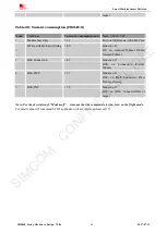
Table 33: Default configuration of GNSS (full on mode)
Item
Configuration
Comment
Baud rate
Depend on firmware
9600/115200bps
GNSS
GPS+GLONASS
GPS/BEIDOU/GLONASS
Update rate
1Hz default
10Hz Max
SBAS
Enable
AIC
Enable
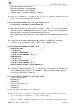
Note: The GNSS modes mentioned above are set by PMTK commands. The PMTK commands for multiple
position chosen are illustrated as below:
$PMTK353,1,0,0,0,0*2A (GPS only)
$PMTK353,0,0,0,0,1*2A (BEIDOU only)
SIMCOM
CONFIDENTIAL
FILE

