Smart Machine Smart Decision
SIM868_Series_Hardware_Design_V1.06
29
2017-07-13
this case, the serial port is still accessible, but partial AT commands and correlative to RF function and SIM
card function will not be accessible.
For detailed information about AT command “AT+CFUN=<fun>“, please refer to document [1].
5.4.1.1.
Sleep Mode 1 (AT+CSCLK=1)
Customer can control GSM to enter or exit the sleep mode (AT+CSCLK=1) by DTR signal. When DTR is in
high level and without interrupt (on air and hardware such as GPIO interrupt or data in serial port), GSM will
enter sleep mode automatically. In this mode, GSM can still receive paging or SMS from network but the serial
port is not accessible.
5.4.1.2.
Wake Up GSM from Sleep Mode 1
When GSM is in sleep mode 1(AT+CSCLK=1), the following methods can wake up the GSM:
Pull down DTR pin
The serial port will be active after DTR pin is pulled to low level for about 50ms
Receive a voice or data call from network
Receive a SMS from network
Receive external interrupt
Note: After module has received incoming call or new SMS, serial port can report URC, but it cannot input AT
command. Only after the DTR pin is pulled to low level for 50ms, the serial port can input AT command.
5.4.1.3.
Sleep Mode 2 (AT+CSCLK=2)
In this mode, GSM will continuously monitor the serial port data signal. When there is no data transfer over 5
seconds on the RXD signal and there is no on air and hardware interrupts (such as GPIO interrupt), GSM will
enter sleep mode 2 automatically. In this mode, GSM can still receive paging or SMS from network.
5.4.1.4.
Wake Up GSM from Sleep Mode 2
When GSM is in sleep mode 2 (AT+CSCLK=2), the following methods can wake up the module:
Send data to GSM via main serial port (the first character will lose).
Receive a voice or data call from network.
Receive a SMS from network.
Note: Autobauding is default. It cannot enter sleep mode in the absence of synchronous serial port baud rate
after GSM power on.
5.5.
Serial Port of GSM
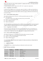
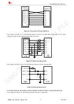
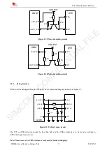
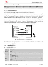
GSM default provides one unbalanced asynchronous serial port and one three-line serial port.
Table 9: Serial port pin definition
Pin name
Pin number Function
Serial port
UART1_DTR
6
Data terminal ready
UART1_RI
7
Ring indicator
UART1_DCD
5
Data carrier detect
UART1_CTS
4
Clear to send
UART1_RTS
3
Request to send
SIMCOM
CONFIDENTIAL
FILE

