background image

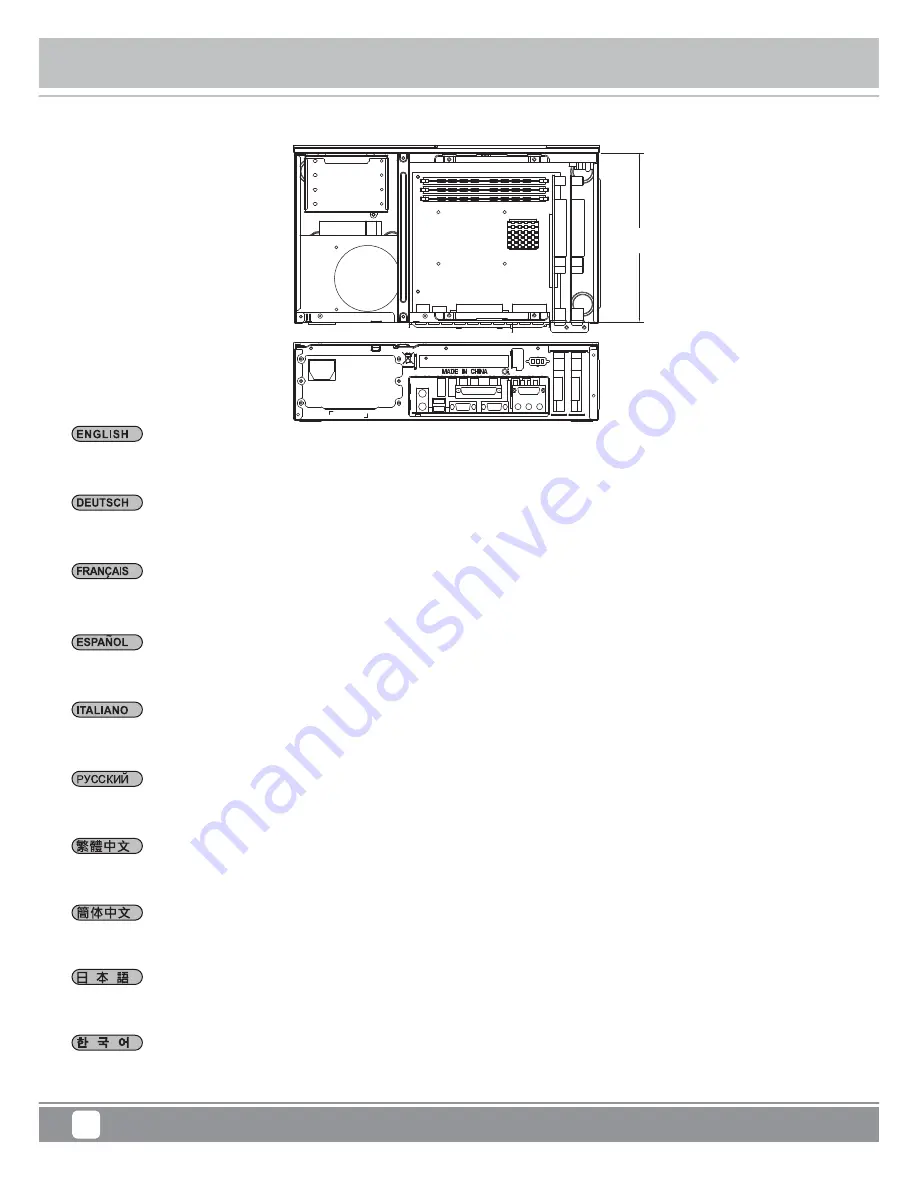
Component size limitations

 Milo 

Series

ML06-E

23

Das ML06-E Low-Profile-Erweiterungskarten mit einer Länge von bis zu 17,52 cm aufnehmen. Standard-Low-Profile-Karten 
sind üblicherweise nur 16,76 cm lang - dadurch passen nahezu alle Arten von Low-Profile-Karten in das ML06-E.

La ML06-E puede acomodar tarjetas de expansión de perfil bajo de hasta 6,9” de longitud. Las tarjetas normales de perfil bajo suelen 
tener solo 6,6” de longitud, luego la ML06-E debería poder instalar cualquiera de estas tarjetas.

ML06-E può alloggiare schede di espansione a basso profilo lunghe fino a 175,2mm. Le schede low profile standard sono generalmente 
lunghe soltanto 167,6mm quindi, all’interno di ML06-E, possono essere installate quasi tutte le schede low profile.

ML06-E can accommodate low profile cards up to 6.9”.  Standard low profile cards are usually only 6.6” long so ML06-E should fit nearly 
any low-profile card on the market.

ML06-E 

можно


установить


платы


расширения


малых


размеров


длиной


до

 6,9 

дюймов

Стандартные


платы


малого


размера


обычно


имеют


длину

 6,6 

дюйма

поэтому

 ML06-E 

должен


поддерживать


практически


все


типы


плат


малого


размера

.

ML06-E은 6.9”까지 LP 형태의 확장 카드를 지원합니다.일반적인 LP 카드의 경우 대부분 6.6” 의 길이를 갖고 있어 ML06-E은 거의 
대부분의 LP 카드 장착이 가능합니다.

ML06-E 支援最長6.9”長的Low profile擴充卡。一般規範的Low profile擴充卡長度只有6.6”,所以任何的Low profile介面卡應當
都可以安裝。

ML06-E 支持最长6.9”长的Low profile扩展卡。一般规范的Low profile扩展卡长度只有6.6”,所以任何的Low profile适配卡应当
都可以安装。

ML06-Eは長さ最大6.9インチのロープロファイル拡張カードを装着できます。

標準のロープロファイル拡張カードは通常、

長さ6.6インチに

過ぎないので、

ML06-Eにはほとんど全てのタイプのロープロファイルカードが搭載可能です。

Le ML06-E peut accueillir des carte d'extension low profile jusqu'à 6.9” de long. Les cartes low profile standard ont habituellement 
une longueur de seulement 6.6” long donc le ML06-E pourra accueillir tous les types de cartes low profile.

(3) Expansion card limitation

190

Summary of Contents for ML06-E

Page 1: ...Milo Series The Mini ITX HTPC benchmark ML06 E ...

Page 2: ...wer Supply Expansion Card Dimension Extra 7mm aluminum front panel 0 8mm steel body SST ML06B E black Mini DTX Mini ITX Exposed Internal Side Top 2 USB 3 0 x 2 audio x 1 MIC x 1 37 70mm variable based on use of multipurpose bracket 1 x Optional standard SFX Single or dual slot low profile up to 6 9 width restriction 2 95 350mm W x 99 mm H x 205 mm D 7 liters Support Kensington lock 9 5mm 12 7mm sl...

Page 3: ...PPER BAG SCW 6 32 SCW M3 SCW M2 RUBBER FOOT RUBBER BUTTOM FOOT SPRING RUBBER FAN RUBBER PADDING USER INSTALLATION GUIDE CONTAINS PARTS AND SCREWS CABLE MANAGEMENT FAN FILTER FOR TOP COVER 120MM FAN SLOT CONTAINS FF143 FILTER AND MANUAL SECURE MOTHERBOARD PSU AND 3 5 DRIVES SECURE 2 5 DRIVES SECURE 9 5MM 12 7MM SLIM SLOT LOADING OPTICAL DRIVE HORIZONTAL ANTI VIBRATION BOTTOM RUBBER FEET VERTICAL ST...

Page 4: ...en Sie die drei Schrauben von der Rückseite des Gehäuses entfernen Sie dann die obere Abdeckung Destornille los tres tornillos de la parte posterior del chasis y luego retire la cubierta superior Svitare le tre viti sul retro dello chassis per rimuovere il cover superiore Unscrew three screws from the rear of the chassis then remove the top cover Отвинтите три винта с задней части корпуса затем сн...

Page 5: ...llos del soporte central para retirarlo Svitare le due viti dal sostegno centrale per rimuoverlo Unscrew two screws from the center brace to remove it Отвинтите два винта с центральной скобы чтобы снять ее 중심 브레이스에서 두개의 나사를 풀어 제거합니다 鬆開中支架2顆螺絲 卸下中支架 松开中支架2颗螺丝 卸下中支架 センターブレースからネジ2本を外して 取り外します Dévissez les deux vis fixant la barre centrale pour la retirer ...

Page 6: ...del disco duro para retirarlo Svitare le viti del supporto hard drive per rimuoverlo Unscrew screws from the hard drive bracket to remove it Отвинтите винты с держателя жесткого диска чтобы снять его 하드 드라이브 브라켓을 제거하기 위해 나사를 제거합니다 鬆開硬碟架螺絲 卸下硬碟架 松开硬盘架螺丝 卸下硬盘架 ハードドライブブラケッ トのネジを外して 取り外します Dévissez les vis du casier à disques durs pour le retirer ...

Page 7: ...ly in two different orientations If you use SilverStone s SFX power supply you must install it with the 80mm fan facing up For more information regarding power supply size limitations please refer to the component guide in later pages Установите источник питания в корпус Обратите внимание что можно установить источник питания в двух разных направлениях При использовании блока питания SilverStone S...

Page 8: ...hmen Sie die Mehrzweckhalterung heraus Retire el bracket multipropósito Rimuovere la staffa multiuso Remove the multipurpose bracket Снимите мно гоцелево й кронштейн 다목적 브래 킷을 분리합니다 拆卸多功能磁架 拆卸多功能磁架 多目的ブラケッ トを取り外します Retirez le crochet multifonction ...

Page 9: ...il pannello I O della scheda madre quindi la scheda madre stessa Insert the I O shield included with your motherboard then install the motherboard into the case Установите панель ввода вывода материнской платы затем установите материнскую плату в корпус 메인보드와 동봉된 I O 커버를 삽입한 후 메인보드를 케이스에 설치합니다 塞入I O彈片 裝入主機板 塞入I O弹片 装入主机板 マザーボードに付属のI Oシールドを装着してから ケース内にマザーボードを取り付けます Insérez la plaque des ports E S i...

Page 10: ...to plan for cable routing before connecting them to the motherboard fan cables 24pin cable CPU ATX 4pin EPS12V 8pin front I O connectors and USB 3 0 connector На этом шаге рекомендуется продумать как будут проложены кабели до их подсоединения к материнской плате кабели вентилятора 24 контактный кабель источника питания 4 контактный кабель ЦП ATX 8 контактный EPS 12 В разъемы на передней панели и п...

Page 11: ...ssa Depending on your requirements install a slot loading slim optical drive 3 5 drive or 2 5 drive onto the multipurpose bracket If additional cooling is not needed the fan can also be removed В зависимости от требований установите на универсальный кронштейн тонкий оптический привод с щелевой загрузкой 3 5 или 2 5 дюймовый жесткий диск Если дополнительное охлаждение не требуется вентилятор можно ...

Page 12: ...el bracket multipropósito de nuevo en el chasis Reinstallare la staffa multiuso nel telaio Reinstall the multipurpose bracket back into the chassis Установите м но гоцелевой кронштейн в корпус 다목적 브래킷을 섀시에 도로 설치합니다 將多功能磁架裝回機殼 将多功能磁架装回机壳 多目的ブラケッ トをケースに戻します Réinstallez le crochet multifonction à l arrière du châssis ...

Page 13: ...drive da 2 5 Installare gli hard drive da 2 5 nel supporto Remove 2 5 drive cage and install 2 5 hard drives into the drive cage Извлеките кронштейн для 2 5 дюймовых жестких дисков Установите 2 5 дюймовые жесткие диски в кронштейн для жестких дисков 2 5 드라이브 케이지를 제거합니다 2 5 하드 드라이브를 드라이브 케이지에 설치합니다 安裝2 5 硬碟到2 5 硬碟架上 安裝2 5 硬碟架 安装2 5 硬盘到2 5 硬盘架上 安装2 5 硬盘架 2 5インチドライブケージを取り外します ドライブケージに2 5インチハードドライブを装着...

Page 14: ... coperchio dell alloggio di espansione ed installare la scheda grafica o la scheda di espansione necessaria Remove expansion slot cover and install required graphics or expansion card Снимите крышку слота расширения и установите нужную графическую карту или плату расширения 확장 슬롯 커버를 제거하고 필요한 그래픽 카드나 확장 카드를 설치하십시오 移除擴充槽檔板並安裝顯示卡或擴充卡 移除扩展槽檔板并安装显示卡或扩充卡 拡張スロッ トカバーを外し 必要なグラフ ィ ックスまたは拡張カードを装着します Enlevez...

Page 15: ... Gehäuse an Reinstale el soporte central en la carcasa Reinstallare il sostegno centrale nel case Reinstall center brace back into the case Установите ц ен тральную скобу обратно в корпус 중심 브 레이스를 케이스에 재 설치합니다 將中支架裝回機殼 将中支架装回机壳 ケースにセンターブレースを戻します Réinstallez la barre centrale dans le boîtier ...

Page 16: ... cover superiore ed assicurarlo allo chassis con le tre viti rimosse in precedenza per completare l installazione Place the top cover back onto the case and secure with three screws to complete installation Завершите установку установив верхнюю крышку обратно на корпус и закрепив тремя винтами 상부 커버를 케이스에 재 장착후 3개의 나사로 고정시켜 설치를 마칩니다 將上蓋裝回機殼 完成組裝 将上盖装回机壳 完成组装 ケースに上部カバーを戻し 3つのネジ3本で固定すると インストールは完成です ...

Page 17: ... il supporto per l orientamento verticale Depending on requirement or preference use rubber feet for horizontal orientation or stand for vertical orientation В зависимости от ваших требований или предпочтений установите резиновые опоры для использования в горизонтальном положении или вертикальную стойку для использования в вертикальном положении 요구사항 또는 취향에 따라 수평 방향의 경우 고무 받침대를 사용하거나 수직 방향의 경우 스탠드...

Page 18: ...aca base la configuración de pines del Conector de panel frontal ó Conector de panel de sistema de su placa base Los interruptores de encendido y reseteo no tienen polaridad luego se pueden conectar con cualquier orientación Guida all installazione dei connettori Power Switch e Reset Switch Fare riferimento al manuale della scheda madre nella sezione Connettori del pannello frontale o Connettori d...

Page 19: ...anel frontal ó Conector de panel de sistema de su placa base Los cables de color blanco negro son negativos mientras que los de color son positivos Los cables LED de potencia tienen pines separados para compatibilidad con diferentes definiciones de pines de la placa base luego por favor asegúrese de que están conectados en la polaridad correcta consultando el manual de su placa base Fare riferimen...

Page 20: ...simplificar la instalación Ниже приведено описание контактов передних разъемов ввода вывода Обратитесь также к руководству пользователя материнской платы за описанием передних разъемов ввода вывода типа пин хедер Разъемы ввода вывода SilverStone блочного типа что облегчает сборку Di seguito lo schema delle connessioni I O frontali confrontare lo schema con quanto riportato sul manuale della scheda...

Page 21: ...os en el bracket multipropósito Por favor consulte la tabla siguiente La limitazione dell altezza del dispersore di calore CPU varierà in base ai componenti installati sulla staffa multiuso Fare riferimento alla tavola che segue CPU Cooler height limitation will vary depending on the component installed on the multipurpose bracket Please refer to the table below Отвинтите три винта с задней части ...

Page 22: ... of a 120mm x 25mm fan and 3 5 drive the illustration shows their relative positions over the motherboard for reference If they overhang a USB 3 0 header on the motherboard it could prevent the installation of USB 3 0 cable На рисунке показано размещение на универсальном кронштейне 3 5 дюймового диска и 120 мм вентилятора На рисунке показано относительное расположение вентилятора с размерами 120 x...

Page 23: ...ore standard SFX con una profondità di 100 mm ML06 E supports standard SFX power supply with up to 100m depth only Корпус ML06 E совместим со стандартными блоками питания SFX глубиной 100 мм ML06 E는 100mm 깊이의 표준 SFX 전원 공급장치를 지원합니다 ML06 E限定使用長度為100mm的標準SFX電源 ML06 E限定使用长度为100mm的标准SFX电源 ML06 E は標準SFX電源 100 深 に対応しています Le ML06 E supporte une source d alimentation SFX standard avec une profondeur de 100...

Page 24: ... 9 Standard low profile cards are usually only 6 6 long so ML06 E should fit nearly any low profile card on the market ML06 E можно установить платы расширения малых размеров длиной до 6 9 дюймов Стандартные платы малого размера обычно имеют длину 6 6 дюйма поэтому ML06 E должен поддерживать практически все типы плат малого размера ML06 E은 6 9 까지 LP 형태의 확장 카드를 지원합니다 일반적인 LP 카드의 경우 대부분 6 6 의 길이를 갖고...

Page 25: ...ot in terms of thickness If 80mm x 15mm fans are installed on the side panel a dual slot card can still be used However with 80mm x 25mm fans installed there will only be enough room for a single slot card Для размещения карты расширения с учетом толщины предусмотрено пространство 50 мм При установке вентиляторов с размерами 80 x 15 мм на боковой панели можно использовать карту с двумя слотами Одн...

Page 26: ...t loading optical drives Below are examples of 12 7mm and 9 5mm optical drives Корпус ML06 E допускает только установку тонких оптических приводов со щелевой загрузкой Ниже приведены примеры оптических приводов толщиной 12 7 мм и 9 5 мм ML06 E은 슬립 슬롯 방식의 광드라이브만 지원합니다 아래의 예는 12 7 mm 및 9 5 mm 광학 드라이브의 예입니다 ML06 E 只能使用吸入式薄型光碟機 以下是12 7mm與9 5mm的光碟機範例供您做參考 ML06 E 只能使用吸入式薄型光驱 以下是12 7mm与9 5mm的光驱范例供您做参考 ML...

Page 27: ...hics card as opposed to the CPU area If you plan on utilizing the multipurpose bracket for drives the fan must be removed so please make sure that your CPU has low enough power output to cope with less airflow Тонкий вентилятор с размерами 120 x 15 мм уже установлен в заводских условиях на универсальном кронштейне для обеспечения нужного охлаждения в большинстве случаев В отличие от корпуса ML06 д...

Page 28: ...talled PSU we recommend cleaning the PSU filters regularly every three months or half a year depending on your environment Illustration We recommend removing and applying filter by hand Рисунок пример блока питания неисправность которого вызвана загрязнением фильтров пылью Для обеспечения длительного и эффективного использования блока питания рекомендуется регулярно выполнять очистку его фильтров ...

Page 29: ...slot Located near the first expansion slot of the case there is a cutout in the shape of a VGA D sub connector this is designed to help save the use of an expansion slot that may otherwise be taken up by the connector in a two slot low profile configuration Паз в форме разъема VGA D sub расположен рядом с первым слотом расширения в корпусе и предназначен для обеспечения возможности использования с...

Page 30: ... the VGA D sub cutout from the case and install the VGA D sub connector The case s cutout supports mounting of the connector in both orientations so you may choose one that best suit your graphics card s requirement 1 Используйте шестигранную отвертку для снятия разъема стандартного размера графической карты 2 Сделайте паз VGA D sub в корпусе и установите разъем VGA D sub Паз в корпусе позволит ус...

Page 31: ...e warranty period please contact your retailer reseller SilverStone authorized distributors or SilverStone http www silverstonetek com Please note that i You must provide proof of original purchase of the product by a dated itemized receipt ii You shall bear the cost of shipping or otherwise transporting the product to SilverStone authorized distributors SilverStone authorized distributors will be...

Page 32: ...G11223600 ...

Reviews: