


- 8 -
Evaluation Kit
SiRad Easy® r4, SiRad Easy® & SiRad Simple®
User Guide
Version 2.5
19-Nov-2021
3.2.1
Serial/USB Data Connection
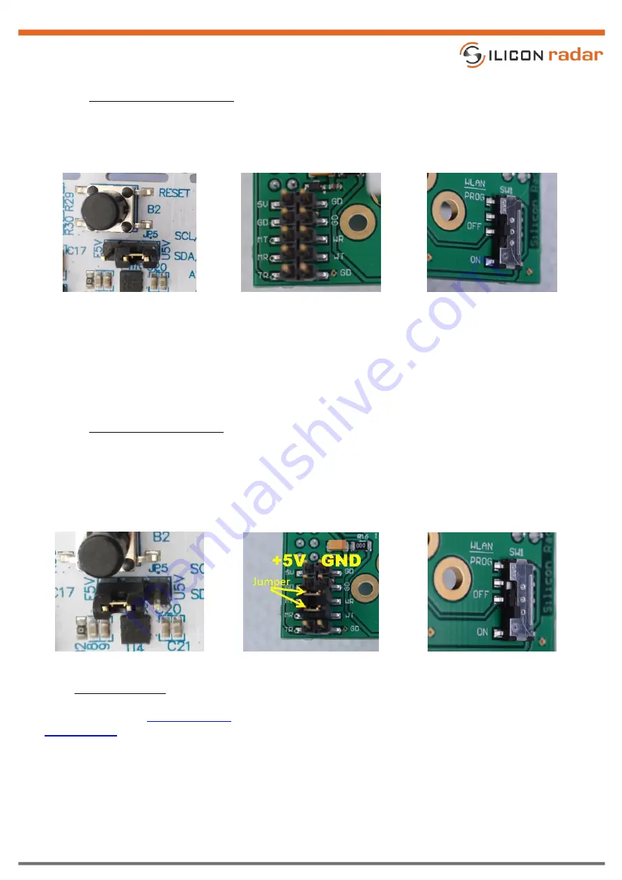
Put jumper JP5 on the microcontroller board in the U5V setting as shown in Figure 9 (left). Remove all jumpers
from the external header (J1) on the baseband board shown in Figure 9 (middle). Bring the WiFi switch SW1 on
the baseband board in the OFF position as shown in Figure 9 (right).
Figure 9
Hardware configuration for Serial/USB connection
SiRad Easy® can now be connected to a PC using a USB cable.
We recommend using an active USB Hub between the PC and SiRad Easy®.
Alternatively, the board can be powered by a 5V DC power supply via the external header (pins 5V and any of the
four GD pins).
3.2.2
Wireless Data Connection
In WiFi mode, the external header (J1) is used to connect the WiFi module to the microcontroller on the board.
Put jumper JP5 on the microcontroller board in the E5V setting as shown in Figure 10 (left). Use jumpers to
connect the MT/WR and MR/WT lines of the external header (J1) on the baseband board as shown in Figure 10
(middle). Apply power from a DC source: +5V to the 5V pin and GND to the any GD pin of the external header (J1).
Bring the WiFi switch SW1 on the baseband board in the ON position as shown in Figure 10 (right).
Figure 10
Hardware configuration for WiFi connection
3.3
Firmware Update
Please also see the
Wiki page for detailed information about firmware updates and the
to download esptool for updating the WiFi firmware.