


- 7 -
Evaluation Kit
SiRad Easy® r4, SiRad Easy® & SiRad Simple®
User Guide
Version 2.5
19-Nov-2021
3
Hardware Setup SiRad Easy®
3.1
Changing the Radar Front End
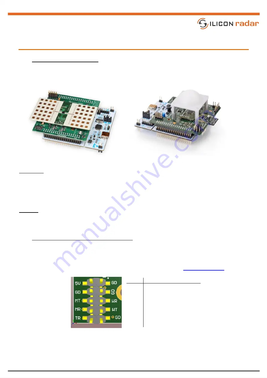
Figure 6 and Figure 7 show the SiRad Easy® with 24 GHz and 122 GHz radar front end boards mounted. Follow the
instructions below for changing the front end board.
Figure 6
24 GHz configuration
Figure 7
122 GHz configuration with lens assembled
Disassembly
Disconnect the power from the Evaluation Kit.
Remove the radar front end from the top of the baseband board. Grab the short edges and pull it straight
out of its connections. Do not tilt or bend the front end. You don’t need to remove the baseband board
from the microcontroller board to exchange the front end board.
Assembly
The radar front end can only be connected one way since the connector pins are different. Slightly press it
down and make sure no pins are bent during the process.
3.2
Data Connection Mode - External Header (J1)
The external header in Figure 8 is used to connect to the sensor board in different operating modes (data transfer
over Serial/USB or WiFi). In programming mode, the external header is used to program either the WiFi module
or the microcontroller, please see Section 3.3. The external header can also be used to trigger measurements
manually via the trigger line (TR), also see the section about trigger options in the
Pin
Description
5V
+5V
GD
GND
MT
microcontroller TX
*
MR
microcontroller RX
*
TR
external trigger line
*
WT
WiFi TX
*
WR
WiFi RX
*
(*) 3.3V tolerant only!
Figure 8
External header (J1) pinout