Silicon Radar EasyRadar User Manual Download Page 8


EasyRadar Sensor Evaluation Kit 
 

- 8 - 

2.4  Software Installation 

The evaluation software is displayed in a Web Browser which supports WebGL.  
We recommend the following Browsers: 
Chrome, Firefox. 

2.4.1 Connecting to the board using a wireless LAN connection 

Due to the wireless LAN connectivity of the module, the installation process is very straightforward. 
On  power-up  the  module  searches  for  the  last  saved  WiFi  access  point.  This  is  indicated  by  the 
rapidly flashing blue LED. If there is no known WiFi access point (AP) accessible, the WiFi module 
opens an own AP. This is indicated by the slowly flashing blue LED on the module (40 secs).  
Please connect to this AP using the following login credentials: 
SSID: 

EasyRadar


Password: 

Greetings


The module is now in AP mode and waits for 40 seconds until it starts the Radar application.  
If the connection is successful, the blue LED is switched off. 
Please find out the IP of the module by checking your DHCP server (WLAN AP). 
The module can now be used as described in chapter 3. 

2.4.2 Connecting the board via USB 

Connecting the board via USB is only supported for Windows systems at this time. 
To connect the board via USB, the ST Microelectronics Virtual Com Port driver has to be installed 
first. Please download it from the ST Webpage: 

http://www2.st.com/content/st_com/en/products/development-tools/software-development-
tools/stm32-software-development-tools/stm32-utilities/stsw-stm32102.html


or from the Silicon Radar download page: 
[link] 
 
The second step is to install a 32-bit Java Runtime Environment from: 

http://www.oracle.com/technetwork/java/javase/downloads/jre8-downloads-2133155.html


Please make sure you select a 32-Bit driver or the communication will not work. 
 
Thirdly,  run  the  Com2WebSocket  application  after  changing  the  path  in  the  runme.bat  to  your 
java.exe path. 
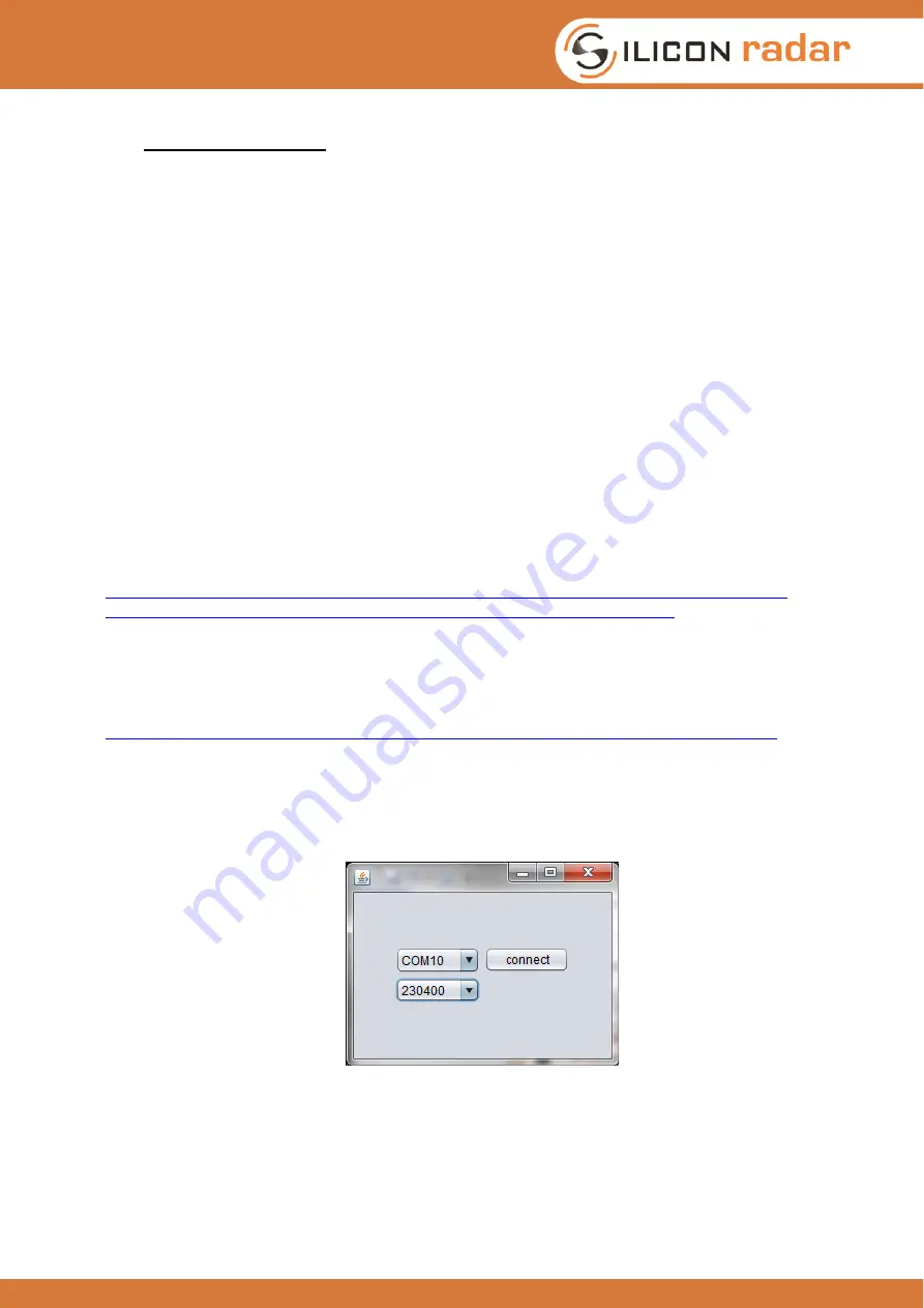
A small window with the available com ports will open: 


Figure 2 

Screenshot of the Websocket-Server window 

 
Please select the appropriate COM port of your Evalkit, and select 230400 baud as the baudrate. 
Then click open. The program then opens a Websocket Server which is fed with the data from the 
com port. 
The Evalkit is now ready to run.  

Summary of Contents for EasyRadar

Page 1: ...Author initial 12 Jul 16 Silicon Radar GmbH Version Document number Filename Page 0 2 RS_120_05 User Guide EasyRadar 1 of 23 Silicon Radar GmbH Im Technologiepark 1 15236 Frankfurt Oder Germany fon 4...

Page 2: ...Sensor Evaluation Kit 9 3 1 The User Interface 9 3 2 Control Panel Sensor Setup 10 3 2 1 COM Panel 10 3 2 2 Sys Config 11 3 2 3 RF params 12 3 2 4 BB processing 12 3 2 5 Target Recognition 12 3 2 6 Sc...

Page 3: ...t of the Websocket Server window 8 Figure 3 Main window of the EasyRadar WebGUI 9 Figure 4 Screenshot of the main GUI window and elements in the display scene 16 Figure 5 Signal flow of the firmware D...

Page 4: ...he EasyRadar Evaluation Kit demonstrates the performance and parameters of the different Radar transceiver chips of Silicon Radar The aim of the evaluation kit is to showcase the FMCW CW radar mode us...

Page 5: ...TRX24 chips Analog signal conditioning to amplify and filter the I and Q output signals of the transceiver Analog to Digital converter to digitize the I and Q receiver signals Microcontroller to do PL...

Page 6: ...on the baseband board connects to CN7 on the micro controller board and CN10 connects to CN10 Improper connections may cause shortcuts and destroy the boards The RFE Board must be attached to the base...

Page 7: ...ition 2 3 Control Header The control header is used to connect to the board in different modes In programming mode it is used to program the WiFi module or the Controller In WiFi mode it is used to co...

Page 8: ...now be used as described in chapter 3 2 4 2 Connecting the board via USB Connecting the board via USB is only supported for Windows systems at this time To connect the board via USB the ST Microelectr...

Page 9: ...oped to demonstrate the functionality of Silicon Radars Transceiver chips as a millimeter wave distance and velocity sensor front end Once the WebGUI is launched the main window is displayed see Figur...

Page 10: ...is used to connect to the server send data to the server and to change the view It contains the following elements COM Sys Config Log RF Params BB Processing Target Recognition Scene Controls 3 2 1 C...

Page 11: ...derive detection threshold for targets against noise This frame contains the CFAR threshold Phase frame A frame containing the values of the phase angles for each range bin argument of the FFT output...

Page 12: ...and the number of samples ADC Clock Divider sets the sampling frequency a higher value means slower sampling Number of samples samples per ramp Number of ramps number of ramps integrated to improve S...

Page 13: ...the camera angle Middle click drag or moving the mouse wheel changes the zoom setting z coordinate of the camera Reset view resets camera rotation and position CamPosX camera position on the X axis m...

Page 14: ...within one range bin It can be used to display relative motion in the m range 3 4 Status field and Target list Statusfield distance in mm cm bin the format which the sensor specifies in the statusfram...

Page 15: ...g wave and incoming wave If the target is moving this value should change rapidly Speed Radial velocity of the target m s calculated as a range difference since the last measurement 3 5 Phase Diagramm...

Page 16: ...ht trigger a false target detection of the CFAR operator Around 60 cm to 180 cm there might be some clutter which is rejected by the CFAR operator Around 200cm there is the first ceiling echo which sh...

Page 17: ...o the application There are too many different parameters which can be optimized to give a one fits all setting from the beginning 5 1 1 Too many targets CFAR doesn t work No targets detected although...

Page 18: ...g red and green As soon as the flashing stops the board is programmed and after a reset the new firmware should be running 6 2 WiFi Module Connect the sensor using a 3 3V USB to UART cable like shown...

Page 19: ...out assy drawings Figure 7 Assembly drawings of the module PCBs 7 3 Changing Hardware Parameters Depending on the type of application it may be necessary to change the filter characteristics and gain...

Page 20: ...aw data output See for details 8 3 Register Description Figure 9 Register definition of the sensor module The sensor accepts commands and setup data as input The registers are 32 bit wide and configur...

Page 21: ...n dB for the target data and the CFAR operator threshold Target List Frame activated by the TL bit in RFE_CONFIG The target list is returned consisting of the o selected format o the baseband amp gain...

Page 22: ...dar Sensor Evaluation Kit 22 UID uint96 96 bit UID extracted from the processor s UID bit field This frame is returned after a successful change of configuration Figure 10 Communication protocol defin...

Page 23: ...d to unusual physical thermal or electrical stress Silicon Radar GmbH makes no warranty of any kind express or implied with regard to this material and specifically disclaims any and all express or im...

Reviews: