


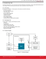


10.4 Test System Connection Procedure
Wire the system as indicated above. All WSTK adapters will be connected to the PC through USB. One adapter will connect to the
DUT, to both reprogram and interact with the DUT, whereas the second adapter will connect to the Golden Node for testing network
functionality. The adapters connected to the DUT should never be turned off. Instead, the DUT will be powered from the isolated Power
Supply for live current measurements.
Within the shielded box the only items protruding inward should be the connectors linked to the DUT, the connectors for 50 Ω antennas.
If desired, a spectrum analyzer may be procured and integrated into the system to measure frequency offset.
10.5 Configuring the WSTKs
For this setup, the PC will communicate to the WSTK with a serial connection. The WSTK will enumerate as a “COM Port” device when
connected to the PC via USB without any additional setup.
10.6 Communicating with Targets
For testing purposes, the NodeTest firmware image will be used on the target DUT. The PC will communicate with the DUT’s UART
interface through the WSTK’s COM port. Use a serial connection tool, such as PuTTY, to start a serial console connection to the
WSTK’s enumerated COM port with the following settings:
• Speed (baud): 115200
• Hardware flow control: enabled
• Data bits: 8
• Parity: none
• Stop bits: 1
Once connected, pressing Enter or sending a “\n” character will result in a prompt ending with a “>” character. Type “help” then press
Enter to display a list of available test functions in Test firmware.
UG171: ZigBee
®
Smart Outlet Reference Design (RD-0051-0201) Kit User's Guide
Manufacturing Tests
silabs.com
| Smart. Connected. Energy-friendly.
Rev. 0.1 | 19