background image

Si5340-EVB

10

Rev. 1.0


Verify Free-Run Mode Operation

Assuming no external clocks have been connected to the INPUT CLOCK differential SMA connectors (labeled

"INx/INxB") located around the perimeter of the EVB, the DUT should now be operating in free-run mode, as the
DUT will be locked to the crystal in this case.

You can run a quick check to determine if the device is powered up and generating output clocks (and consuming
power) by clicking on the 

Read All

 button (the bottom-right of Figure 14) and then reviewing the voltage, current,

and power readings for each VDDx supply.
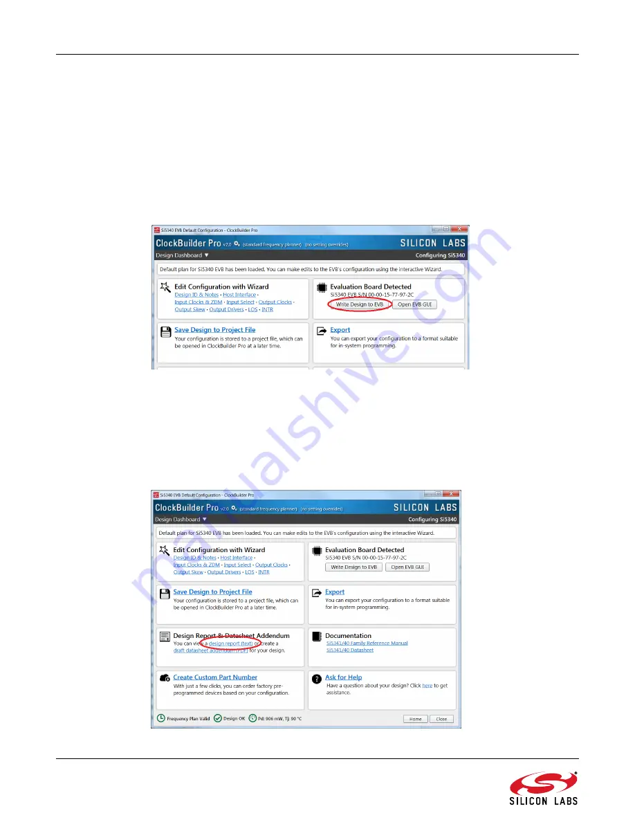
Note:

Shutting the VDD and VDDA power supplies "Off" and then "On" will power-down and reset the DUT. Every time you do
this, to reload the Silicon Labs-created default plan into the DUT's register space, you must go back to the Wizard's main
menu and select 

Write Design to EVB

:

Figure 15. Write Design to EVB

Failure to do the step above will cause the device to read in a pre-programmed plan from its non-volatile memory (NVM).
However, the plan loaded from the NVM may not be the latest plan recommended by Silicon Labs for evaluation.

At this point, you should verify the presence and frequencies of the output clocks (running in free-run mode from

the crystal) using appropriate external instrumentation connected to the output clock SMA connectors. To verify the
output clocks are toggling at the correct frequency and signal format, click on 

View Design Report 

as highlighted

in Figure 16.

Figure 16. View Design Report

Summary of Contents for Si5340-EVB

Page 1: ...gured using the Clock Builder ProTM CB ProTM software tool Features Powered from USB port or external power supply Onboard 48 MHz XTAL allows free run mode of operation on the Si5340 or up to 3 input...

Page 2: ...ck diagram of the Si5340 EVB This EVB can be connected to a PC via the main USB connector for programming control and monitoring See Section 3 Quick Start or Section 9 Installing ClockBuilderPro CBPro...

Page 3: ...u can use ClockBuilderPro to create download and run a frequency plan on the Si5340 EVB 5 For Si5340 data sheet go to http www silabs com timing 4 Jumper Defaults Si5340 EVB Jumper Defaults Location T...

Page 4: ...EDs showing on board MCU activity Figure 2 Status LEDs Si5340 EVB Status LEDs Location Silkscreen Color Status Function Indication D5 INTRB Blue DUT Interrupt D7 LOLB Blue DUT Loss of Lock D8 LOSXAXBB...

Page 5: ...ow The REFCLK can then be applied to J25 and J26 Figure 3 External Reference Input Circuit 7 Clock Input Circuits INx INxB and FB_IN FB_INB The Si5340 EVB has eight SMA connectors IN0 IN0B IN2 IN2B an...

Page 6: ...ted on the Si5340 EVB and provide locations on the PCB for optional DC AC terminations by the end user Figure 5 Output Clock Termination Circuit 9 Installing ClockBuilderPro CBPro Desktop Software To...

Page 7: ...B GUI Figure 7 Application 1 ClockBuilderPro Wizard Use the CBPro Wizard to do the following Create a new design Review or edit an existing design Export create in system programming Figure 8 Applicat...

Page 8: ...in more detail in the following sections 10 3 1 Workflow Scenario 1 Testing a Silicon Labs Created Default Configuration The flow for using the EVB GUI to initialize and control a device on the EVB i...

Page 9: ...t plan for the DUT type mounted on the EVB Figure 12 Writing Design Status 5 After CBPro writes the default plan to the EVB click on Open EVB GUI as shown in Figure 13 Figure 13 Open EVB GUI 6 The EVB...

Page 10: ...wer down and reset the DUT Every time you do this to reload the Silicon Labs created default plan into the DUT s register space you must go back to the Wizard s main menu and select Write Design to EV...

Page 11: ...Your configuration s design report appears in a new window shown in Figure 17 Compare the observed output clocks to the frequencies and formats noted in your default project s Design Report Figure 17...

Page 12: ...ro Wizard click on Edit Configuration with Wizard Figure 18 Edit Configuration with Wizard You are then taken to the Wizard s step by step menus which allow you to change any of the default plan s ope...

Page 13: ...tion 1 To test a previously created user configuration open the CBPro Wizard by clicking on the icon on your desktop and then selecting Open Design Project File Figure 21 Open Design Project File 2 Lo...

Page 14: ...tten to the device verify the presence and frequencies of your output clocks and other operating configurations using external instrumentation 10 4 Exporting the Register Map File for Device Programmi...

Page 15: ...Si5340 EVB Rev 1 0 15 You can now write your device s complete configuration to file formats suitable for in system programming Figure 25 Export Settings...

Page 16: ...he I2C mode of operation SPI mode was chosen for the EVB because of the relatively higher speed transfers supported by SPI vs I2C 12 2 External I2C Support I2 C can be supported if driven from an exte...

Page 17: ...The Si5340 EVB Schematic and Bill of Materials BOM can be found online at http www silabs com products clocksoscillators pages si538x 4x evb aspx Please be aware the Si5340 EVB schematic is in OrCad...

Page 18: ...Si5340 EVB 18 Rev 1 0 DOCUMENT CHANGE LIST Revision 1 0 Initial Release...

Page 19: ...assumes no responsibility for errors and omissions and disclaims responsibility for any consequences resulting from the use of information included herein Additionally Silicon Laboratories assumes no...

Reviews: