Operating manual - English
BRAVO MAXIMA II
Copyright Silca 2011
15
Fig. 14
A
XIS
CALIBRATION
:
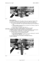
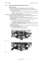
Axis calibration is regulation of the cutting space on the key (fig. 12, page 14); proceed as follows:
1) Turn off the master switch (C) to operate safely and prevent activation of the cutting tool.
2) Position the electric contact templates on the clamps (fig. 13, page 14) and proceed as follows:
a) ensure that the keys adhere to the clamps and that the callipers (K) are in full contact with the
stops.
b) to take the callipers into contact with the keys, rotate the drum (R) towards you (away from
you to return to the ideal position).
c) Press the I/O key on the display in order to turn it on.
d) Press the MODE key; the display will show the word OFF (no contact).
ATTENTION: the carriage will be released only if the callipers are in the ideal position.
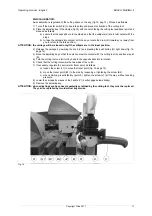
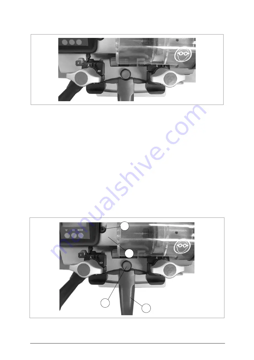
3) Release the carriage by lowering the knob (V) and pressing the push button (Q) right down (fig.15).
4) Take the right-hand side of the templates in contact with the cutter and tracer point.
5) The display should show the word ON; if not, proceed as follows:
a) loosen the screw (J1) to move the tracer point (fig.15).
b) move the tracer point support (B1) sideways by loosening or tightening the screw (B2)
(fig.18, pag.17) until ON appears.
c) tighten the screw (J1) all the way, without exerting pressure.
6) Lower the carriage by means of the handle (V) (it will engage automatically).
7) Remove the templates.
Fig. 15
J1
B1
Q
V
Summary of Contents for Bravo Maxima II
Page 1: ...Operating manual D432446XA vers 5 0 EN...
Page 4: ......

