


10
MBA1000
Datum 26.08.2008
Art.Nr. 79828
Änd. Stand 318/08
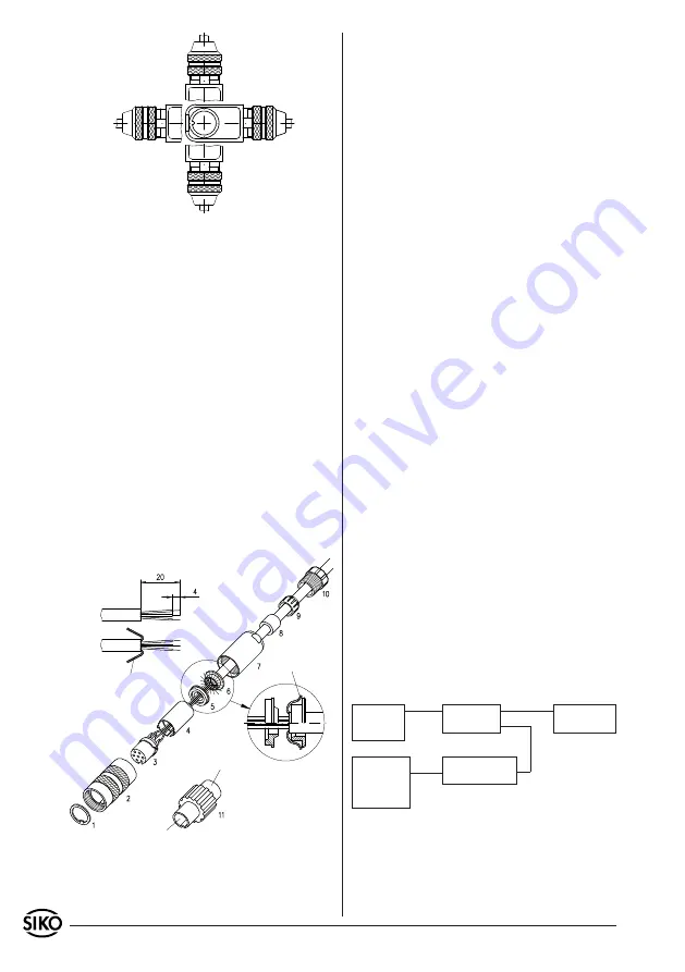
Fig. 9: Angled postions
screening
screening
socket
pin
Fig. 10: Programming of SIKO display
MA10/3
SSI:
Data format = no; encoder bits = 24; singleturnbits
= irrelevant; output code = Gray
Programming of SIKO display
MA10/4
SSI: encoder
type = linear; encoder bits = 24; factor = 1.0 (1mm
display); output code = Gray
+24V/GND
MSA1000
cycle+/cycle-/
data+/data-
eg. MA10/3
SSI
RS232
RXD/TXD/RTS/GND
level converter
RS232 <-> RS485
RS485
DÜA/DÜB/GND
power pack:
24VDC/
500mA
PC
Connection type E4/.. with coupling (socket)
Slip parts 6 to 10 over outer cable.
Strip cable.
Turn down screening.
Push part 5 onto ferrules.
Solder stranded wires at part 3 (follow connec-
tion diagram).
Open spacer (part 4) and put it over ferrules,
squeeze and push it onto part 3. Slot and keyway
of parts 3 and 4 must align.
Press parts 6 and 5 together; cut prodruding
screening.
Push parts 2 and 7 together and screw part 11
using appropriate tool.
Push part 8 into part 9 and slide both parts
into part 7.
Screw parts 10 and 7 together.
Push part 1 into part 2.
1.
2.
3.
4.
5.
6.
7.
8.
9.
10.
11.
Moderate self-heating of the sensor is normal and
no reason to worry.
Sensor and magnetic strip need not be electrically
aligned, as programming is already carried out by
the manufacturer. Even if the magnetic strip is ex-
changed later a re-alignment is not necessary.
5.1 Sensor programming
Certain parameters of sensor MSA1000 are program-
mable via its RS485 interface and are non volatile,
but can nevertheless be modified at any time.
Please proceed as follows:
Use a level converter (eg. type I-7520 from Spec-
tra company) to establish a connection between
your PC's serial RS232 interface and the sensor's
RS485 interface.
Switch on the sensor's power supply and start with
programming by:
using a suitable terminal program (eg. sikoterm.
exe) and by manually entering your commands
accord. to the table "list of commands – service
operation of MSA1000" (see chapter 7). Please
remember that your terminal has to be adjusted
to the pre-programmed interface parameters.
or
using the terminal tool "demo1000.exe" which
allows to enter your parameters via the function
keys and to display at the same time all relevant
encoder data. There are further parameters which
allow additonal functions within the program
demo1000.
Either ask at SIKO for the programs sikoterm.exe
and demo1000.exe and for additional information
for the user or download the current version from
the Internet:
http://www.siko.de/download
5.2 Application examples for sensor programming
and display of the position value
•
•
5. Commissioning
After correct mounting of the magnetic strip and
sensor (see chapter 3) and completion of all wiring
work (see chapter 4) the system is ready for use.