


10 MSK500/1
+MB500/1+MR500
Datum 12.05.2015
Art.Nr. 81413
Änd. Stand 87/15
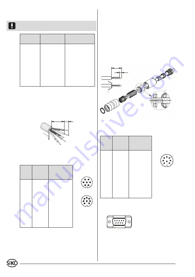
as short as
possible
screening
Fig. 8: Connection type E1
viewing side =
plug-in side
plug pin
viewing side =
plug-in side
plug pin
Fig. 9: Mounting connection type E6
screening
screening
viewing side = plug-in side
plug pin
4.2 Connection type / Pin outs
E1:
Flying leads.
Attention!
Tinned strands must not used in combi-
nation with screw/clamp connections.
Signal
inverted
inverted with
reference signal
A
red
red
B
orange
orange
I, R
- - -
blue
+UB
brown
brown
GND
black
black
A/
yellow
yellow
B/
green
green
I/, R/
- - -
violet
1. Remove cable coating.
2. Open screening and twist it.
3. Strip stranded wires to a length of 5mm and
twist them.
4. Pinch stranded wires
6. Open spacer (part 4) and put it over ferrules,
squeeze and push it onto part 3. Slot and keyway
of parts 3 and 4 must align.
7. Press parts 6 and 5 together; cut prodruding
screening.
8. Push parts 2 and 7 together and screw.
9. Push part 8 into part 9 and slide both parts
into part 7.
10. Screw parts 10 and 7 together.
11. Push part 1 into part 2.
E6:
Connection with plug pin and socket contact.
Plug mounting according to fig. 9.
Signal inverted inverted with
reference
signal
A
Pin 1
Pin 1
B
2
2
I, R
- - -
3
+UB
4
4
GND
5
5
A/
6
6
B/
7
7
I/, R/
- - -
8
nc
3
- - -
1. Slip parts 6 to 10 over outer cable.
2. Strip cable.
3. Turn down screening.
4. Push part 5 onto ferrules.
5. Solder wires to part 3 (according connection
diagram).
E7:
Connection with 8 pole coupler plug.
Signal inverted inverted with
reference
signal
A
Pin 1
Pin 1
B
2
2
I, R
- - -
3
+UB
4
4
GND
5
5
A/
6
6
B/
7
7
I/, R/
- - -
8
nc
3, 8
- - -
E8:
Connection with 9 pole D-SUB plug pin and so-
cket contact.