background image

22

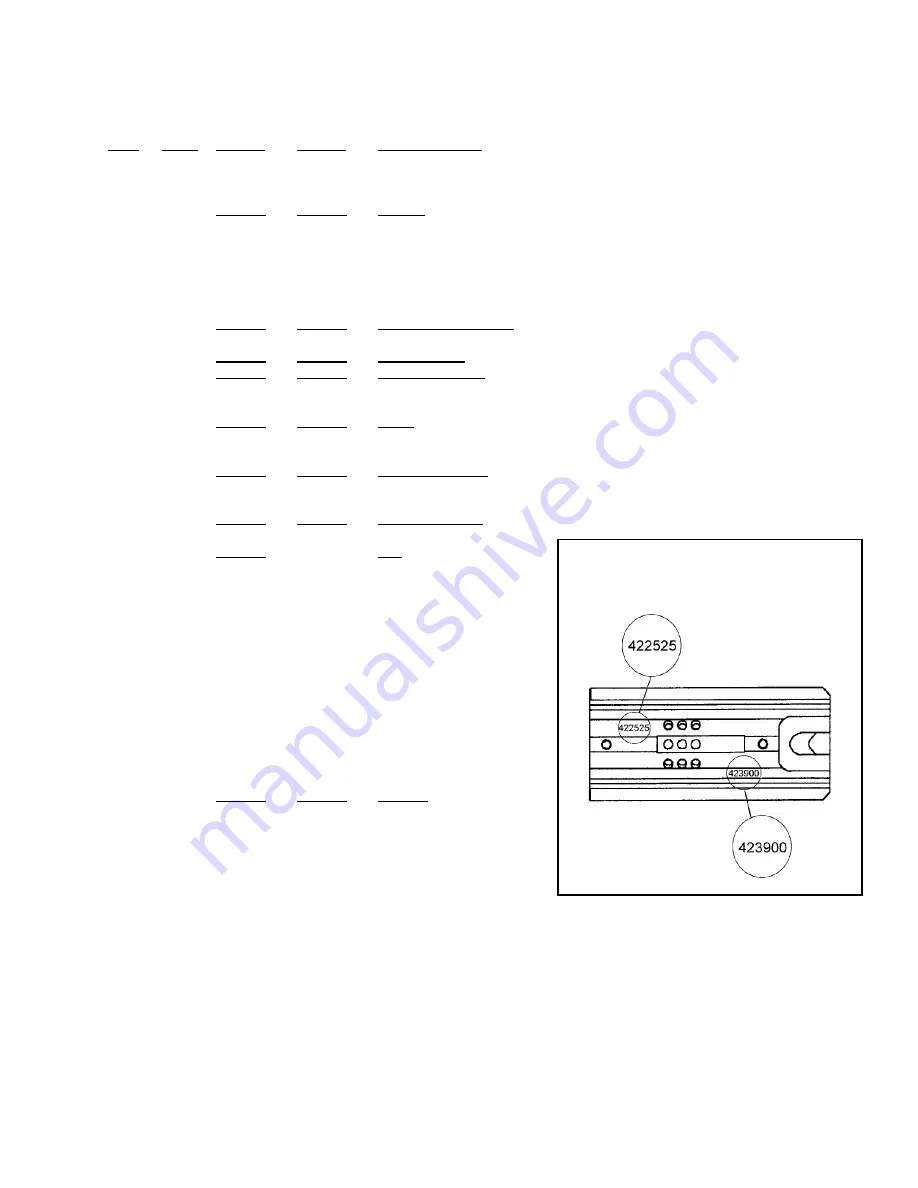
   These air motors can be identified by
   inspecting the part number shown on
   the underside of Key 11 (Mtr Housing).

PARTS LIST, AIR MOTORS: IR95R17V (422525) & 95R17V (423900)

422525

423900

KEY

QTY.

PART#

PART#

DESCRIPTION

 1

 1

020704

020704

Quick disconnect plug

 2

 1

422501

024631

Filter assembly

 3

 2

273822

273822

Fitting

 4

 1

306838

306838

Retaining ring

 5

 1

422502

306831

Valve sleeve

 6

 2

020699

020699

O-ring

 7

 1

422503

306832

Valve stem

 8

 5

094295

094295

O-ring

 9

 1

422521

024661

Spring

10

 1

004658

004658

Roll pin 1/8 x 13/16

11

 1

422595

422595

Motor housing

13

 1

024633

024633

Ball bearing

14

 1

422505

023515

Back end plate

15

 1

422506

023517

Cylinder

16

 1

422507

023510

Align pin

17

 5

422508

024651

Vane

18

 1

422524

423423

Rotor

19

 1

     -

024602

Spacer

20

 1

422510

090074

Front end plate

21

 2

023481

023481

Ball bearing

22

 1

023552

     -

Ball bearing

23

 3

422526

024605

Idler assembly

24

 1

422527

090081

Cage (cage assembly)

25

 3

422528

     -

Pin

26

 1

422514

     -

Retainer

27

 1

422515

024608

Ring gear

28

 1

023551

023551

Seal 

29

 1

023556

023556

Pin

30

 1

422516

090078

Gear housing

31

 1

422594

422594

Motor cover

32 

 3

012298

012298

SHCS, 8-32 x 5/8

33

 1

273818

273818

Pilot valve

34

 1

023446

023446

O-ring

35

 1

273845

273845

Valve cap

36

 1

422529

422529

Valve housing assy

37

 2

274438

274438

Screw

38

 1 

422593

422593

Motor control lever

39

 1

422542

273821

Tubing, 6-5/8" Lg

40

 1

422520

422520

Spacer

41

 1

280522

280522

Info tag (Hansen Plug)

42

 1

422598

422598

Throttle valve cap

43

 1

422597

422597

Throttle valve

44

 1

422596

422596

Spring

45

 1

274442

274442

Fitting

46

 1

422532

422532

Spring

47

 1

422535

422535

Adjustment screw

48

 1

422536

273821

Tubing, 9" Length

49

 1

422546

273821

Tubing, 8" Length

50

 1

435824

435824

Information sign

51

 2

     -

090004

Belleville washer

52

 1

     -

423151

Spacer

53

 1

433395

433395

Information Tag (Air Pressure)

!

When ordering parts, please show Air Motor number and description.

!

Standard hardware parts may be obtained from any local hardware supply. 

!

Wearing parts are usually limited to those underlined and should be stocked.

Summary of Contents for TENSION-WELD VXT2-16

Page 1: ...VXT2 16 19 TENSION WELD STRAPPING TOOL...

Page 2: ...during tensioning and sealing can result in severe personal injury from flying strap or tool When tensioning or sealing position yourself to one side of the strap and keep all bystanders away Using st...

Page 3: ...s repairs or cleaning of the tool disconnect air supply This tool is a Tension Weld type sealer A properly made joint will appear as shown in the illustration If the joint does not appear as shown the...

Page 4: ...nformity 35 VXT2 16 Part No 422580 VXT2 19 Part No 422585 SPECIFICATIONS MODEL STRAP TYPE WIDTH THICKNESS VXT2 16 High Strength Tenax 16mm 629 0 036 to 0 044 0 91 1 11mm VXT2 19 High Strength Tenax 19...

Page 5: ...the adjustment screw Key 47 on the Air Motor Assembly counter clockwise as required AIR SUPPLY INSTALLATION If compressor has a good dryer unit use black pickled pipe When a dryer unit is not installe...

Page 6: ...is removed at the water leg in the piping system or in the filter Part No 008559 NOTE Additional information is available in the Signode publication Air Supply Manual Part No 186038 If you have any qu...

Page 7: ...least 600 lbs 2664N of tension is drawn at 90 psig 6 2 Bar Strap breakage hazard Strap can break if inlet air pressure to tool exceeds 90 psig 6 2 bar Strap breakage can result in severe personal inju...

Page 8: ...a indoor located Filter Regulator Lubricator or relocate the F R L to a warmer operating area AIR PRESSURE DROP Confirm air pressure calibration by comparing it to a master gauge placed in line where...

Page 9: ...ing lever and while standing to one side of the strap line squeeze the motor control lever to tension the strap 3 When the motor stalls indicating completion of tension continue to hold the motor leve...

Page 10: ...EALING OPERATION This tool is a Tension Weld type sealer A properly made joint will appear as shown in the illustration If the joint does not appear as shown then the operator must proceed as follows...

Page 11: ...produce an acceptable joint or if you have any questions as to whether your tool is producing good weld strength contact your Signode Sales Representative CUTTER ADJUSTMENTS When the strap cutter beg...

Page 12: ...at the shims while rotating Clearance between the feedwheel and gripper plug at this point should fall between 002 004 05 10mm 3 If the feedwheel needs to be adjusted use a 3 32 hex wrench to rotate t...

Page 13: ...e marked 16 or 19 2 The guide spacer key 105 must also be repositioned for the appropriate strap size Squeeze the tensioner foot lever to expose the SHCS Key 104 on the tensioner foot Temporarily remo...

Page 14: ...21 6 Lift the torsion spring 23 and the tensioner foot 16 off the support pin 25 This allows the gripper plug 17 to be replaced if necessary Turn the tensioner foot over remove the flat head cap screw...

Page 15: ...so as not to damage or lose the spring 7 Examine the cutter blade 46 spring 84 and pin 74 for a worn or damaged areas Replace if necessary 8 Reassemble the tool in reverse order except for the small...

Page 16: ...screw through the bearing into spacer 86 Clamp the screw head in a vise and lightly tap the casting to extract the bearing See inset A 5 Examine the teeth of the lower gripper 78 If the part is to be...

Page 17: ...gs with the concave side towards the washer 32 Stake the spacer sleeve twice and replace the spacer sleeve subassembly 6 Assemble the clutch spring 36 and the clutch 37 on the spline of the Spiroid wo...

Page 18: ...reful not to damage the air lines Remove the O ring 34 from the end of the air motor housing Set it to the side for reuse 3 Remove the three socket head cap screws which secure the motor mount to the...

Page 19: ...plate 14 and the rotor assembly 18 with the vanes 17 out of the cylinder 11 Look for areas of wear on the face of the end plates the pinion teeth on the rotor and the edges of the vanes The vanes must...

Page 20: ...stall the O ring valve housing assembly drive gear bearing and lower air motor cover 20 The air motor mount assembly can now be mounted to the gear housing assembly 21 Lift up the cutter blade and ins...

Page 21: ...on has been reached Air also flows to and stops at the 3 way valve 3 The weld handle is pulled back initiating the welding cycle Air is directed to the throttle valve opening it fully allowing full ai...

Page 22: ...y 25 3 422528 Pin 26 1 422514 Retainer 27 1 422515 024608 Ring gear 28 1 023551 023551 Seal 29 1 023556 023556 Pin 30 1 422516 090078 Gear housing 31 1 422594 422594 Motor cover 32 3 012298 012298 SHC...

Page 23: ...Secure with Loctite 569 or equivalent The pilot valve Key 33 must only be serviced by an authorized Signode Service Facility or a maintenance person trained by Signode NEVER remove the pilot valve wh...

Page 24: ...1 306869 Pin 48 1 422108 Slider link 49 1 273850 Lift tab 50 1 273842 Pin 51 1 422110 Pin pivot 52 1 422109 Upper gripper 53 1 273820 Flow control 54 2 274442 Fitting 56 1 273819 3 way valve 58 1 273...

Page 25: ...25...

Page 26: ...ld identified by an incomplete area of weld 8 Incomplete or no weld 9 Strap is over welded 10 Motor shut off is sluggish 11 Strap weld time is erratic 12 Weld time is too long CUT OFF ACTION 13 The cu...

Page 27: ...tor from the tool and disassemble it If these parts are only dirty clean thoroughly oil and reassemble If they are worn or rusted replace them 4 CONDITION Feedwheel milling on strap and or strap break...

Page 28: ...sm by brushing away the strap residue or washing the entire unit in a solvent When a solvent is used it is imperative the assembly be blown dry to remove all solvent Check for dry or worn bearings in...

Page 29: ...e tool of all excess oil See instructions Excess Oil Removal found in this manual 13 CONDITION The cut off has become difficult CAUSE REMEDY 1 Strap residue jamming cutter mechanism 2 Adjust cutter as...

Page 30: ...he weld time is too long and seemingly cannot be adjusted the tool may have an excessive amount of oil internally Purge the tool of the excess oil as follows 1 Open the flow control fully by turning t...

Page 31: ...w for the appropriate configuration for the tool application NOTE Each hanger is supplied with two 10 24x3 4 socket head cap screws Part No 008731 for mounting the hanger to the tool VERTICAL STORAGE...

Page 32: ...seful for applications which are close to the floor where the standard pneumatic connection and supply hose could get in the way KEY QTY PART NO DESCRIPTION 1 1 020710 Elbow 90 2 1 004154 Hose 3 1 086...

Page 33: ...33...

Page 34: ...34...

Page 35: ...fined in EC Directive 89 392 EEC Machine Supplier Signode Division of ITW Ltd Queensway Fforestfach Swansea SA5 4ED Machine Description VXT2 Series Machine Type Pneumatic Combination Hand Strapping to...

Page 36: ...the tool is in Signode s possession for warranty repairs This warranty is void as to any tool which has been I subjected to mis use misapplication accident damage or repaired with other than genuine...

Reviews: