background image


Alarm   

Cause 

Solution 


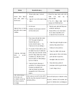
DL AGC Alarm


AGC Alarm


1.  High  input  level  at the  BTS  port  of 

the  booster,  AGC  is  active  and 

more  than  20dB  attenuation  has 

been applied. 

2.  An  isolation  condition  may  also 

have occurred. 

1. 

Add the RF attenuator in BTS port to 

decrease  the  input  power.  And 

decrease  the  downlink  gain  by 

adjusting the downlink attenuation.   

2. 

Increase  the  separation  distance  of 

the  donor  and  service  antenna.  And 

then  adjust  the  gain  to  meet  the 

isolation issue. 

DL Low O/P Alarm


1.  DL input power of booster is low. 

2.  Too  much  attenuation  value  has 

been  set  according  to  insufficient 

isolation. 

3.  Unsuitable setting in OMT. 

4.  Amplifier  inside  the  booster  has 

been damaged. 


1.  Adjust the donor antenna to receive a 

stronger signal. Input signal of booster 

within 

-40dBm 

-60dBm 

is 

recommended. 

2.  Increase  the  distance  between  donor 

and  service  antenna  to  increase  the 

isolation  between  them,  so  that  more 

gain can be used. 

3.  Check  the  OMT,  and  make  sure  the 

DL PA switch is ON and limit value has 

been  set  to  be  20dB  lower  than 

booster

’s  total  output  power.  Refer  to 

OMT User’s Manual 

for more detail. 

4. 

If  all  the  problems  above  don’t  exist, 

please  check  the  output  power  with 

the  spectrum  analyzer.  If  the  output 

power  is  low,  which  cannot  meet  the 

formula:  Output  =  Input  +  Gain, 

booster is damaged. Return the unit to 

place of purchase for repair. 


DL Over O/P Alarm


1.  Extremely  high  input  level  at  the 

BTS  port  of  the  booster.  The 

output  power  has  exceeded  the 
AGC’s control.   

2.  Insufficient  isolation  will  also 

cause this alarm. 

1.  Decrease  the  gain  by  adjusting  the 

relevant  manual  attenuation  or  add  an 

RF  attenuator  at  the  BTS  port  of 

booster  to  decrease  the  input  signal 

power. 

2.  Move  the  location  of  antennas  to 

increase the distance between them. 

Over Temp Alarm 

The  temperature  of  the  booster  is 

above  the  set  threshold,  which  is 

caused 

by 

the 

installation 

Booster  has  to  be  installed  vertically. 

Relocate the booster to a more ventilated 

position. 

Summary of Contents for J4I-CP Series

Page 1: ...J J4 4I I C CP P S Se er ri ie es s I In nd du us st tr ri ia al l S Si ig gn na al l B Bo oo os st te er r U Us se er r s s M Ma an nu ua al l ...

Page 2: ...ine of Available Functions 9 3 Installation 10 3 1 Preparation 10 3 2 Antenna Installation 10 3 2 1 Donor Antenna 11 3 2 2 Service Antenna 12 3 2 3 Isolation 14 3 3 Booster 16 3 3 1 Installing the Booster 16 4 Commissioning 18 4 1 Commissioning Principle 18 4 1 1 Downlink Output Power 18 4 1 2 Isolation 20 5 Maintenance 20 5 1 Alarms and Solutions 20 5 2 Troubleshooting 22 5 3 Booster Replacement ...

Page 3: ...uch failures 1 2 Safety Information Personnel Safety Before installing or replacing any of the boosters the entire manual should be read and understood Operators need to supply appropriate AC or DC power to the booster Incorrect power settings can damage the booster and may cause electrical related injury to the user It is recommended that gloves are worn at ALL times when handling the product DO ...

Page 4: ...at the power outlet In order to avoid equipment damage or human injury by lightning static electricity and other phenomenon of electricity leakage Manufacturer suggest all products must do the electric discharge of the electrical grounding in setup process Power supply components must meet international electro technical commissioning safety standards 1 3 Other Precautions Only authorized personne...

Page 5: ...s using the booster allows mobile phones to establish a connection 2 2 General Installation Layout Figure 1 Outdoor Application Above provides a typical installation layout of an outdoor project The booster is connected via coaxial cables to donor and service antennas The donor antenna is placed on one side of the mountain pointing to the donor BTS to receive the signals The service antenna is pla...

Page 6: ...ents Splitters Splitters are isolated dividers that split or combine RF power According to the coverage requirement splitter can distribute RF power into several paths to achieve coverage of each area In the meantime mobile signals from different coverage areas are combined together and transmitted into the booster Here we recommend some famous brand that with good quality Andrew brand from Commsc...

Page 7: ...ther brand or similar items if clients need to change such items please compare the specifications carefully and consult the professional manufacturer if it s suitable to use the other brand The usage of the unqualified antennas cables or coupling device may result in the improper work of boosters and even damage the device Please double check before changing these items 2 4 Advantages of Booster ...

Page 8: ...the downlink part first which is from BTS to MS Please note that uplink works in the same way except the signal direction is from MS to BTS Figure 4 illustrates the self explanatory signal path after entering into the booster Figure 4 Dual Band Selective Booster When uplink or downlink signal enters the booster it is filtered by duplexer firstly Then the filtered signal enters into LNA in which we...

Page 9: ...l board which displays booster operating and various alarm status At the mean time the UL and DL attenuation can be adjusted to make booster to perform its best via the switch on this board Detailed alarm of the booster can be viewed on the front panel please refer to Section 5 Maintenance for in depth details of each individual alarm condition and their solution 31dB Manual Gain Control During in...

Page 10: ... not face direct sunlight and in a location that stays within 25 to 55 Recommended tools list Table below lists the recommended tools that will be required for a successful installation Item Quantity Item Quantity Signal Generator 1 Spectrum Analyzer 1 Test Mobile 1 Laptop 1 50 Ω load terminator 2 Electrical Drill 1 Multimeter 1 Spanner 2 Hammer 1 Screwdriver 1 Waterproof glue 1 Safety belt 1 RF a...

Page 11: ...a s characteristics ultimately affecting the performance of the booster 4 For outdoor booster antenna s front to back ratio must be higher than 20dB to assure excellent isolation on the site 5 Recommended donor antennas Argus brand from Commscope www commscope com CNNPX306R 6P 16dBi gain or CNNPX308M 4P 17dBi gain While for a safe working conditions of the booster please don t choose any antennas ...

Page 12: ... Service Antenna Selection The service antenna is usually selected and purchased by the customer we will also list some of the popular brand for your option in below It needs to meet the requirements below 1 Working frequency The service antenna needs to be compatible with the booster s operating frequency range 2 Half power Beam width Select the antenna with suitable half power beam width accordi...

Page 13: ...ence of passers by 3 The service antenna should not be installed close to the donor antenna to avoid isolation issues For outdoor coverage the following conditions need to be considered 1 Avoid installing near trees or other obstacles that may influence its coverage performance 2 The service antenna should not be installed too close to the donor antenna to avoid issues with isolation The angle bet...

Page 14: ... to this criterion can result in poor signal to the coverage area and may damage the PA of the booster 3 2 3 1 Self oscillation Concept Isolation is the propagation loss value from the booster s output port to its input port For a wireless booster insufficient isolation between donor and service antennas will result in self oscillation Figure 6 As shown in the above diagram the donor antenna recei...

Page 15: ...of the isolation value a physical measurement may be carried out to obtain the isolation value for the actually environment where the booster is installed The measurement procedures are Connect a signal generator to the donor antenna cable as illustrated below and transmit a known frequency and power level from the signal generator Frequency needs to be within the idle frequency between the uplink...

Page 16: ...e signal generator sends out a signal 1795MHz with 25dBm power level The signal scanned by the spectrum analyzer 70dBm So Isolation 25dBm 70dBm 95dB In this condition to avoid self oscillation the gain of booster must be set to be no more than 80dB which is 15dB lower than the isolation value 3 3 Booster 3 3 1 Installing the Booster 3 3 1 1 Wall Mount Installation There are 2 steps of installing t...

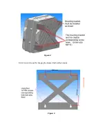
Page 17: ...Figure 8 Drill 4 holes in the wall for hanging the bracket that hold the booster Figure 9 ...

Page 18: ...ink Output Power The total downlink output power of the booster is depending on the input power and the booster gain To ensure the maximum power of the booster is achieved at the MS port of the booster the following condition should be met 4 1 1 1 Gain and Output Power The gain is the amplifying ability of the booster The booster has a constant gain for both uplink and downlink Both uplink and dow...

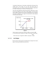
Page 19: ...trol function will be triggered The AGC ensures that the maximum output power of booster is maintained and does not overdrive the booster s amplification circuit Figure 15 demonstrates the relation between the output power and the gain Figure 11 Suppose maximum output power of booster is 37dBm and its gain is 89dB So when input power is weaker than 52dBm output power Input Power 89dB When input po...

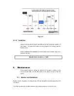
Page 20: ...solation and how to measure the value 5 Maintenance The proceeding section outlines the definition of the alarm conditions on the front panel and OMT and the steps that can be used to rectify or clear the alarms 5 1 Alarms and Solutions When an alarm is triggered its corresponding LED will change to be red and displayed on the front panel The following table lists the different alarms and possible...

Page 21: ...ion between them so that more gain can be used 3 Check the OMT and make sure the DL PA switch is ON and limit value has been set to be 20dB lower than booster s total output power Refer to OMT User s Manual for more detail 4 If all the problems above don t exist please check the output power with the spectrum analyzer If the output power is low which cannot meet the formula Output Input Gain boost...

Page 22: ...annot be solved it means booster has been damaged Please return the damaged FC module to place of purchase for repair Master Power Failure If the booster s AC input is shut down the back up battery inside the booster will work and this alarm will be sent out 1 1 Check whether the power cable has been connected properly and the power outlet are switched on 1 2 Check the power switch of booster Batt...

Page 23: ... of feeder cable system decreases because of oxidization of the cable connector after certain period of usage especially in harsh conditions e g Seaside areas with chemicals or cable damage by mice or insects 3 Change of indoor structure or upholstery The change of indoor structure or upholstery will influence directly the predicted propagation loss in the previous design 1 Check the signal streng...

Page 24: ...ce antenna to increase the isolation And then adjust the booster s gain to the safe value Please refer to Booster Configuration part to see how to set booster s gain properly 5 3 Booster Replacement If the booster needs to be replaced the following procedure is recommended Switch off the power supply Disconnect the power cable Disconnect the RF feeder cables Disconnect the grounding cable of boost...

Page 25: ...occur in a particular installation If this equipment does cause harmful interference to radio or television reception which can be determined by turning the equipment off and on the user is encouraged to try to correct the interference by one or more of the following measures Reorient or relocate the receiving antenna Increase the separation between the equipment and receiver Connect the equipment...

Page 26: ...nverter IF Intermediate Frequency INC Increase LED Light Emitting Diode LNA Low noise Amplifier MS Mobile Station Min Minimum OMT Operation Maintenance Terminal PA Power Amplifier PLL Phase Locked Loop RF Radio Frequency RSSI Receive Signal Strength Indication SIM Subscriber Identity Module TEMP Temperature UL Uplink VSWR Voltage Standard Wave Ratio WCDMA Wide Code Division Multiple Access ...

Reviews: