


Rev 2.0 | SC5309A & SC5310A
Hardware Manual
SignalCore, Inc.
2
SC5309A & SC5310A Hardware Manual
The bulk transfer from the host to the device operates on a loopback with a data buffer of 8 bytes.
When a device register is addressed, and upon completion of the register task, such as changing
frequency, it will send back 8 bytes, which the host must read to clear the transfer buffers. Unlike
the other interface methods, where only the required number of bytes needs to be sent for a given
register, 8 bytes are needed for every USB bulk transfer. For example, if a configuration register
requires only 4 bytes to be sent, these bytes will be the first of the 8 bytes and the last 4 bytes are
zeros. The returned 8 bytes do not carry valid data for a configuration register. However, they do
carry valid data for query registers.
SPI Interface
The SPI interface on the device is implemented using an 8-bit (single Byte) buffer for both the input
and output, hence, it needs to be read and cleared by the device before consecutive bytes can be
transferred to and from it. The process of clearing the SPI buffer and decisively moving it into the
appropriate register takes CPU time, so a time delay is required between consecutive bytes written
to or read from the device by the host. The chip-select pin (
𝐶𝑆
̅̅̅
) must be asserted low before data
is clocked in or out of the product.
Furthermore, pin
𝐶𝑆
̅̅̅̅
must be asserted low for the entire
duration of a register transfer.
Once a full transfer has been received, the device will proceed to process the command and de-
assert low the SRDY pin. The status of this pin may be monitored by the host because when it is de-
asserted low, the device will ignore any incoming data. The device SPI is ready when the previous
command is fully processed and the SRDY pin is re-asserted high. It is important that the host either
monitors the SRDY pin or waits for 500
𝜇𝑠
between register writes.
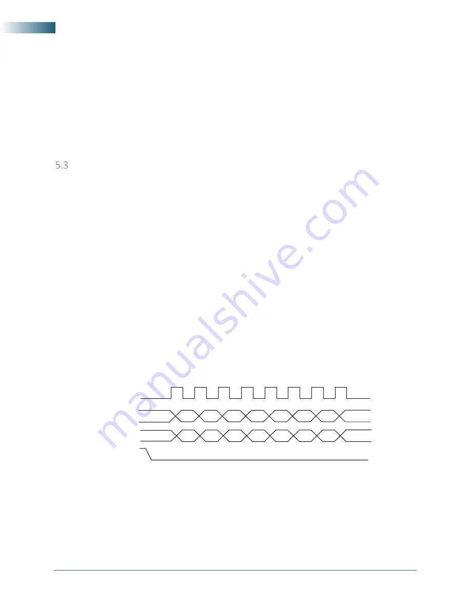
There are 2 SPI modes: 0 and 1. The default mode is 1, where data is clocked in and out of the device
on the falling edge of the clock signal. In mode 0, data is clocked in and out on the rising edge. To
select mode 0, pin 23 of the interface connector must be pulled low to ground as the device is
powered on or as the reset line (pin 19) is toggled low-high. If pin 23 is pulled high or left
unconnected, mode 1 is selected.
Figure 7. SPI Mode 1 shown.
Register writes are accomplished in a single write operation. Register lengths vary depending on the
register. They vary in lengths of 2 to 8 bytes, with the first byte sent being the register address
followed by the data associated with that register. The (
𝐶𝑆
̅̅̅
) pin must be asserted low for a
minimum period of 1
𝜇𝑠
(
𝑇
𝑆
) before data is clocked in, and must remain low for the
entire register write. The clock rate may be as high as 5.0 MHz (
𝑇
𝐶
= 0.2
𝜇𝑠
), however, if the external
SPI signals do not have sufficient integrity due to trace issues, the rate should be lowered.
MSB
CS
MISO
MOSI
CLK
MSB
LSB
LSB