


75 SNA5000A Vector Network Analyzer User Manual
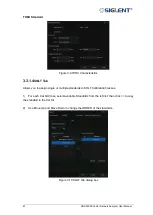
Type of calibration kit Connector,
Female
or
Male
, in the
DUT Connector
, select
TRL
in
the Cal Type, and click
Next
to proceed to the next step.
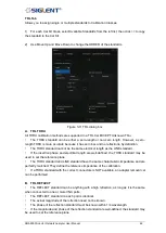
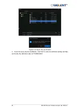
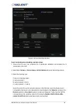
5.
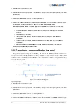
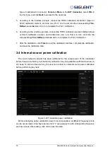
According to the interface prompts, connect the THRU calibration kit, Reflect (Open or
Short) calibration element, and Line on a Port 1 in turn, and click the corresponding
Thru
,
Reflect,
and
Line
items in turn to complete the Port 1 calibration.
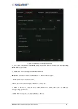
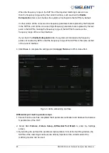
6.
According to the interface prompts, connect the THRU calibration element, Reflect (Open
or Short) calibration element, and transmission line on a Port 2 in turn, and click the
corresponding
Thru
,
Reflect,
and
Line
items to complete the Port 2 calibration.
7.
After the calibration, click
Finish
to exit the calibration interface, complete the calibration,
and save the calibration data.
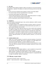
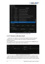
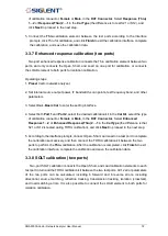
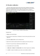
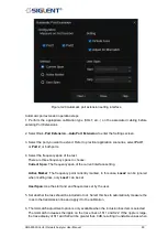
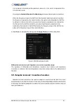
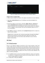
3.4 Internal source power calibration
The vector network analyzer has been calibrated for the output power of the transmitter
before it leaves the factory, but the factory calibration may not guarantee sufficient accuracy in
all cases. To improve the accuracy, the user can conduct an internal source power calibration
before performing any tests.
Figure 3-25 Transmitter power calibration
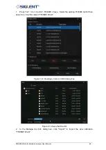
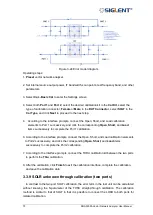
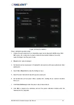
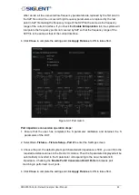
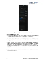
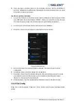
Before attempting power calibration, power loss compensation at different frequency points
can be set as shown in the figure below. Click "+" successively to add corresponding frequency
and loss values. After setting, click OK to save the data.
Summary of Contents for SNA5000A Series
Page 2: ......