


SIG
L
ENT
SDS2000X-E User Manual
83
I2C Trigger and Serial Decode
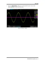
Please read “
Setup for I2C Signals
”, “
I2C Trigger
” and “
I2C Serial Decode
” to trigger
and decode the signals.
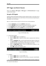
Setup for I2C Signals
Setting the I2C (Inter-IC bus) signal includes two steps: connecting the serial data signal
(SDA) and serial clock signal (SCL) to oscilloscope, specifying the threshold voltage of
each input signal.
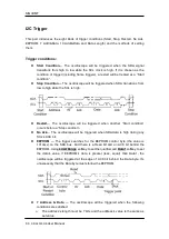
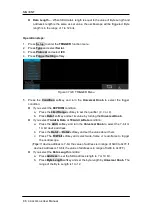
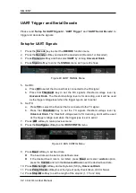
1. Press
Decode
key to enter the
DECODE
function menu as Figure 35 shows.
Figure 35 I2C DECODE Menu
2. Press the
Decode
softkey and select the desired slot (Decode1 or Decode2).
3. Press
Protocol
softkey and then select
I2C
by turning
Universal Knob
.
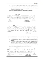
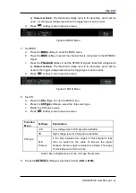
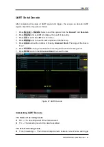
4. Press
Signal
softkey to enter the
SIGNAL
menu as Figure 36 shows.
Figure 36 I2C SIGNAL Menu
5. Set SCL (I2C’s clock signal):
a. Press
SCL
softkey to select the channel that is connected to the I2C clock signal.
b. Press first
Threshold
softkey to set the I2C clock signal’s threshold voltage level
by
Universal Knob
. The threshold voltage level is for decoding, and it will be
regard as the trigger voltage level when set the trigger type to serial.
6. Set SDA (I2C’s data signal):
a. Press
SDA
to select the channel that is connected to the I2C data signal.
b. Press second
Threshold
softkey to set the I2C data signal’s threshold voltage
level by
Universal Knob
. The threshold voltage level is for decoding, and it will
be regard as the trigger voltage level when set the trigger type to serial.
(Tip: SDA should keep stable during the whole high clock cycle, otherwise it will be
interpreted as a start or stop condition (data transitioning while the clock is high).)
7. Press
softkey to return previous menu.
Summary of Contents for SDS2000X-E Series
Page 1: ...User Manual SDS2000X E Series Digital Oscilloscope UM0102E E01A SIGLENT TECHNOLOGIES CO LTD...
Page 14: ......
Page 69: ...SIGLENT SDS2000X E User Manual 43 Figure 13 x Interpolation Figure 14 Sin x x Interpolation...
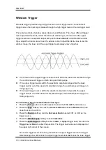
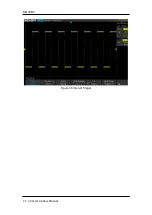
Page 98: ...SIGLENT 72 SDS2000X E User Manual Figure 29 Relative Window Trigger...
Page 100: ...SIGLENT 74 SDS2000X E User Manual Figure 30 Interval Trigger...
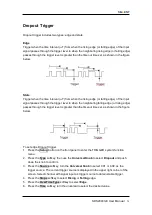
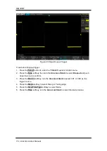
Page 103: ...SIGLENT SDS2000X E User Manual 77 Figure 32 State Dropout Trigger...
Page 105: ...SIGLENT SDS2000X E User Manual 79 Figure 33 Runt Trigger...
Page 125: ...SIGLENT SDS2000X E User Manual 99 Figure 49 CAN Trigger...
Page 129: ...SIGLENT SDS2000X E User Manual 103 Figure 51 LIN Trigger...
Page 162: ...SIGLENT 136 SDS2000X E User Manual...
Page 200: ...SIGLENT 174 SDS2000X E User Manual Figure 95 Built in Arb interface...
Page 206: ...SIGLENT 180 SDS2000X E User Manual Figure 100 WiFi setting menu...
Page 215: ...SIGLENT SDS2000X E User Manual 189 Figure 108 Option Information...