SDG800 User Manual 48
PM
The modulated waveform consists of two parts: the carrier waveform and the
modulating waveform. In PM, the phase of the carrier waveform varies with
the instantaneous voltage level of the modulating waveform. The parameters
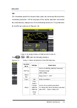
for the PM are as shown in Figure 2- 36.
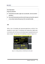
Figure 2- 36 Setting Interface of PM Waveform Parameter
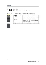
Press Mod →Type →PM, enter the following interface.
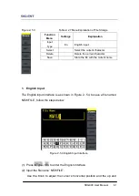
Figure 2- 37 Table 2- 18 Menu Explanations of the PM Parameters
Function
Menu
Settings
Explanation
PM Freq
Set the modulating waveform frequency.
Frequency range:
2mHz~20kHz
Phase
Dev
Range from 0° ~ 360°.
Type
PM
Phase modulation
Shape
Sine
Square
Triangle
UpRamp
DnRamp
Noise
Arb
Choose the modulating waveform.
To change the carrier waveform parameter,
press Sine, Square, Ramp, Arb
Summary of Contents for SDG800 Series
Page 32: ...SDG800 User Manual 22 Figure 2 5 Setting the Offset...
Page 42: ...SDG800 User Manual 32 Figure 2 15 Setting the Rise edge...
Page 83: ...SDG800 User Manual 73 Source Internal...
Page 95: ...SDG800 User Manual 85 Figure 3 1 Sine Waveform...
Page 97: ...SDG800 User Manual 87 Figure 3 2 Square Waveform...
Page 104: ...SDG800 User Manual 94 the wave generated is shown in Figure 3 6 Figure 3 6 Sinc Waveform...
Page 110: ...SDG800 User Manual 100 Figure 3 9 AM Waveform...
Page 112: ...SDG800 User Manual 102 3 10 Figure 3 10 FM Waveform...
Page 114: ...SDG800 User Manual 104 Figure 3 11 PM Waveform...
Page 116: ...SDG800 User Manual 106 Figure 3 12 FSK Waveform...
Page 118: ...SDG800 User Manual 108 Figure 3 13 ASK Waveform...
Page 122: ...SDG800 User Manual 112 Figure 3 15 DSB AM Waveform...


