SIG Kadet Senior Sport Assembly Manual Download Page 4

❑  

(2)  3-1/2” dia. Main Wheels

❑  

(2)  4mm dia. x 62mm Axles

❑  

(2)  7.5mm Hex Nuts; for axles

❑  

(4)  4mm ID Wheels Collars; for axles

❑  

(1)  Right Fiberglass Wheel Pant; painted white

❑  

(1)  Left Fiberglass Wheel Pant; painted white

Tailwheel

❑  

(1)  Tailwheel Assembly, including Wheel, formed Wire, Nylon

           Bearing, and Wheel Collars(2)

❑  

(2)  M3 x 12mm Sheet Metal Screws

Electric Motor Mount

❑  

(1)  Plywood Electric Motor Box Assembly; for electric motors

❑  

(1)  Balsa Triangle Stock; for motor mount reinforcement

❑  

(2)  Velcro® Straps

❑  

(4)  M4 x 20mm Socket-Head Mounting Bolts; for electric

           motor mount to firewall

❑  

(4)  M4 Flat Washers; for electric motor mount to firewall

❑  

(4)  M4 x 16mm Socket-Head Mounting Bolts; for electric

           motor to mounts

❑  

(4)  M4 Split-Ring Lock Washers; for electric motor to mounts

❑  

(4)  M4 Blind Nuts; for electric motor to mounts

Engine Mounts for Glow Engine

❑  

(2)  Nylon Engine Mounts; for glow engines

❑  

(4)  M4 x 20mm Mounting Bolts, for engine mount to firewall

❑  

(4)  M4 Flat Metal Washers, for engine mount to firewall

Fuel Tank for Glow Engine

❑  

(1)  Fuel Tank

❑  

(1)  Rubber Stopper Assembly

❑  

(1)  Fuel Pick-Up Weight, Metal

❑  

(1)  Fuel Line Tubing, for inside tank

❑  

(1)  laser-cut plywood Fuel Tank Support

Control Horns

❑  

(4)  Nylon Control Horns; for ail(2), ele(1), rud(1)

❑  

(2)  Nylon Control Horn Retaining Plates; for ele(1), rud(1)

❑  

(12) M2 x 14 mm Screws; for control horns

Pushrods

❑  

(2)  39-1/2" long Wire Pushrods, threaded on one end, 

           including M2 Hex Nuts(2); for elev. & rud.

❑  

(2)  6-3/4" long Wire Pushrods, threaded on one end, 

           including M2 Hex Nuts(2); for ail.

❑  

(1)  17-3/4" long Wire Pushrod, , threaded on one end, 

           including M2 Hex Nut; for throttle

❑  

(1)  13-3/4" long Nylon Pushrod Tube, for throttle

Miscellaneous

❑  

(1)  19mm OD  x 495 mm Aluminum Tube Main Wing Joiner

❑  

(1)  Molded Clear Plastic Side Window, Right Front

❑  

(1)  Molded Clear Plastic Side Window, Left Front

❑  

(2)  Molded Clear Plastic Side Windows, Rear

❑  

(2)  M6.5 x 30 mm Nylon Wing Bolts with slotted head

❑  

(4)  Metal Clevis; for ail(2), ele(1), rud(1), throttle)1)

❑  

(5)  small pieces of Fuel Tubing; for metal clevis keepers

❑  

(4)  Pushrod Snap Keepers; for ail(2), ele(1), rud(1)

❑  

(4)  M3 x 10mm Sheet Metal Screws, for cowling

❑  

(4)  M3 x 12mm Socket-Head Bolts, for wheel pants

❑  

(3)  M4 x 20mm Socket-Head Bolts, for main landing gear

❑  

(3)  M4 Split-Ring Lock Metal Washers, for main landing gear

❑  

(1)  Metal Pushrod Keeper with Set Screw and Hex Nuts, 

           for throttle servo connector

❑  

(2)  240mm long Plastic Cinch Straps

❑  

(1)  Small Balsa Block; for fuel tank stop

Your KADET SENIOR ARF is covered with Oracover

®, a premium

quality covering made in Germany, and sold in the U.S. by Hanger-
9 as Ultracote

®

.

Colors

Oracover® #10 White (Ultracote® #HANU870)

and

Oracover® #29 Transparent Red (Ultracote® #HANU950)

or

Oracover® #59 Transparent Blue (Ultracote® #HANU954) 

If  sometime  in  the  future  you  need  replacement  covering  or
matching paint for repairs, they are available from your local hobby
dealer or online from Hanger-9.

How To Tighten Loose Covering

After you open your KADET SENIOR and take all the covered
parts out of their plastic bags, the covering may begin to wrinkle.
This is not unusual and is no cause for alarm.  

Your airplane was built and covered in a part of the world which
has relatively high humidity and therefore, the wood was likely car-
rying a fair amount of moisture.  When exposed to drier air, the
wood typically loses this moisture, dimensionally "shrinking" in the
process.  In turn, this may cause some wrinkles.  However, wrin-
kles are easy to remove by just using a hobby type heat iron.  Cau-
tion: Trying to remove the wrinkles by hastily going over them with
a heat gun can lead to more problems.  You should take your time
to carefully go over the entire model with a covering iron, as we
will describe.

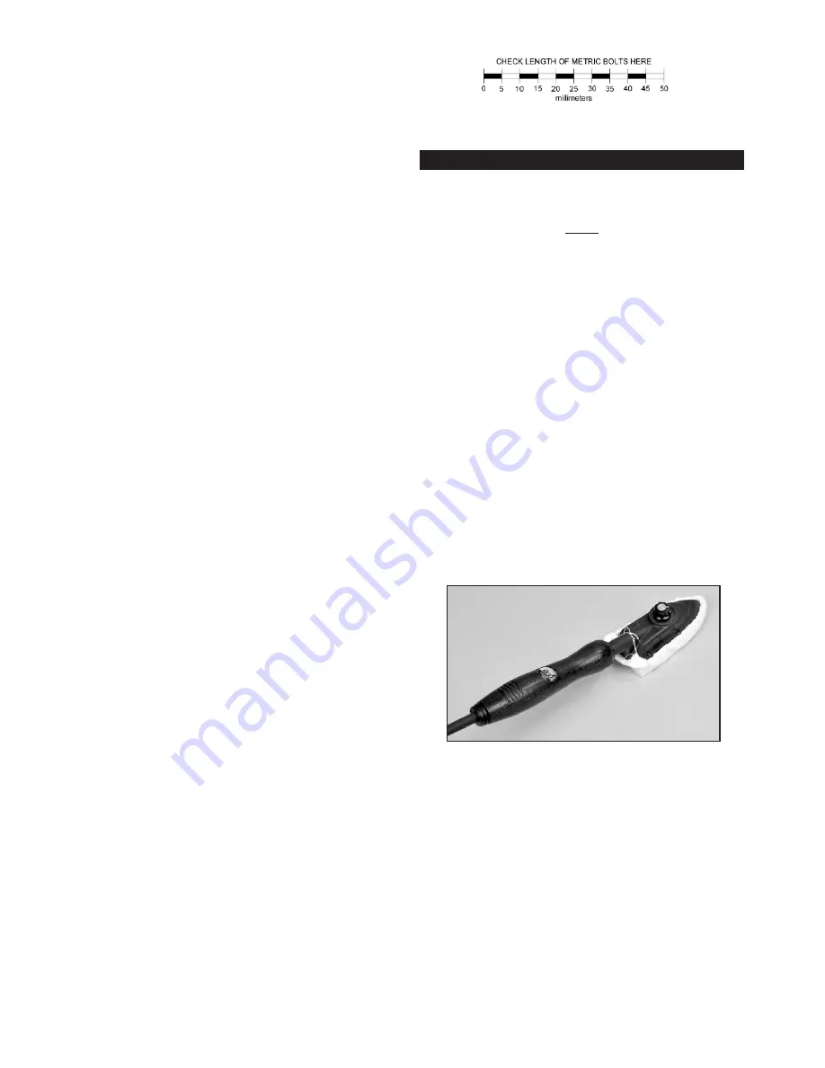
We suggest  using a model airplane covering iron for this process.
Cover the iron's shoe with a thin cotton cloth, such as an old t-
shirt, to prevent scratching the covering as you work.

After covering your iron, the next step is to set the iron to the cor-
rect temperature.  This is critical for achieving a good result!    The
iron should be set to about 

220

O

F - 250

O

F (104

O

C - 121

O

C)

as

measured on the bottom of the iron using a thermometer.  

If you do not have a thermometer, you can find the correct tem-
perature by trial and error.  Set your iron to a medium setting.
Glide the iron over some of the covering that is over over solid
wood, such as the sheeted wing center section.  Observe the cov-
ering to see if any bubbles appear.  If bubbles appear, the covering
is getting too hot!  Turn down the temperature of the iron.
If no bubbles appear, turn up the heat slightly and repeat the test.
Keep adjusting until you “zero in” on the correct temperature.  Find
the temperature that will get the covering to stick down without
forming bubbles or causing the seams to pull away.  

4

COVERING MATERIAL

Summary of Contents for Kadet Senior Sport

Page 1: ...ight 8 8 5 lbs 2720 2950 g Wing Loading 12 0 13 0 oz sq ft 36 39 g dm2 Radio 4 Channel with 5 Standard Servos Glow Power 40 53 cu in 6 5 8 7 cc 2 Stroke Engine 50 61 cu in 8 1 10 cc 4 Stroke Engine Electric Power Brushless Outrunner Motor 600 1100w 500 800kv 42 50mm case dia 60 75A Speed Control ESC 4 6s 4000 5000 mah Lipo Battery Pack Shown with optional 2 Spinner not included ...

Page 2: ...ER MOTOR The KADET SENIOR SPORT has been flown with motors rated from 600 to 1100 watts While this range is quite wide it illlus trates the versatility of the KADET s light wing loading This air plane can fly with minimal power for realistic flight or with extra ASSEMBLY MANUAL INTRODUCTION Congratulations on your purchase of the KADER SENIOR SPORT ARF The SIGKADET SENIOR has a long and illustriou...

Page 3: ...amps and damaging your ESC or motor OUR FLIGHT TEST REPORT After extensive test flying our favorite setup for the KADET SEN IOR is the Himax 5018 530 530 KV brushless motor with a 75 amp ESC 5S 5000 mah lipo battery pack and an APC 12x8E propeller This combination gave outstanding flight performance with flight times around 8 10 minutes depending of course on throttle management Your results may v...

Page 4: ...x Nuts for throttle servo connector 2 240mm long Plastic Cinch Straps 1 Small Balsa Block for fuel tank stop Your KADET SENIOR ARF is covered with Oracover a premium quality covering made in Germany and sold in the U S by Hanger 9 as Ultracote Colors Oracover 10 White Ultracote HANU870 and Oracover 29 Transparent Red Ultracote HANU950 or Oracover 59 Transparent Blue Ultracote HANU954 If sometime i...

Page 5: ... your call The obvious benefit to leaving the wing panels separate is the fact that they can be easily transported or stored To help protect your wings during the following steps we recom mend that you cover your work surface with a soft cloth or piece of soft cell foam INSTALLING THE AILERON SERVOS For the following steps you will need 1 Right Wing Panel 1 Left Wing Panel 1 Aluminum Tube Wing Joi...

Page 6: ...e aileron down and hold it in this position Remove the pins from one hinge and then carefully apply 3 4 drops of Thin CA glue directly onto the hinge in the gap You will notice that the glue is quickly wicked into the slot as it penetrates both the wood and the hinge We suggest using a fine tipped applicator on the glue bottle to better control the flow of glue e Turn the part over and glue the ot...

Page 7: ...Then test fit the wing assembly on the fuselage The tab that is formed by the two panels at the center leading edge fits into the cutout in the front fuselage former At the rear two M6 5 x 30mm nylon wing bolts secure the wing to the fuselage If you encounter any difficulties mounting the wing to the fuselage find the problem and fix it now Then remove the wing from the fuse lage and set it aside ...

Page 8: ...d 1 Fuselage 1 Wing 1 Stabilizer Elevator set 1 Vertical Fin Rudder Set 2 M6 5 Nylon Wing Bolts 1 Tailwheel Assembly 2 M3 x 12 mm Screws 2 Nylon Control Horns with Retaining Plates 6 M2 x 14 mm Screws 12 Remove the elevator and hinges from the stabilizer and el evator and set them aside for now Test fit the stabilizer on the fuselage Notice that the covering has been removed from both the fuselage...

Page 9: ...u get to the 90 degree bend rotate the wire up so you can continue to slide the long shank of the wire inside the fuselage c Keep sliding the wire in until the short top leg exits the slot in the stabilizer d Hold the nylon tailwheel bearing in place on the bottom of the fuselage Mark the mounting hole locations and then drill 1 16 dia pilot holes in the fuselage Then screw the bearing in place wi...

Page 10: ...e servo opening in the front right side of the tray is for the throttle servo in a glow installation Be sure to drill pilot holes through the plywood tray for the mounting servo mounting screws 22 Mount your receiver in a place of your choosing If using a glow engine it is recommended that you wrap the receiver in foam rubber to protect it from vibrations 23 If you are using a receiver battery pac...

Page 11: ...he back of the clevis 25 Locate the pushrod exit hole for the elevator inside the rear of the fuselage and repeat step 24 in its entirety to install the el evator pushrod Skip this section if your using a glow engine power setup For this section you will the Fuselage and 1 Fiberglass Cowling 4 M3 x 10mm Screws 1 Plywood Electric Motor Mount 1 Balsa Triangle Stock 4 M4 x 20mm Socket Head Bolts 4 M4...

Page 12: ... of the firewall to line up with the marks Make sure you end up with the firewall straight and square in the box If it is not recheck your marks and adjust as necessary e Tack glue the firewall in place Recheck once more to make sure that the front of the firewall is at the correct distance from the back of the motor mount box That distance plus the length of your motor must equal 4 1 4 When satis...

Page 13: ...rop shaft is centered in the hole Use low tack tape to hold the cowling in place for the next step b Use a 5 64 or 45 bit to drill a pilot hole for the top left cowl mounting screw Center the drill in the hole in the cowling and drill into the fuselage side Install an M3 x 10mm screw in the pilot hole do not over tighten the screw c Recheck the position of the cowling and make any adjust ments nee...

Page 14: ... Hex Nut 1 Metal Pushrod Keeper with Set Screw and Hex Nuts 1 Metal RC Clevis 1 small piece of Fuel Tubing for clevis 2 Hook Loop Velcro Straps You will also need to acquire these items not supplied 1 R C Engine and suitable Propeller 4 Socket Head Engine Mounting Bolts to fit engine 4 Lock Nuts for engine mounting bolts 4 Flat Metal Washers for engine mounting bolts 3 6 in lengths of Silicone Fue...

Page 15: ... Double check to make sure that the engine is pointing exactly straight forward and then carefully mark the locations of the engine mounting holes on to the beams of the engine mounts 41 Now set your engine aside and unbolt the engine mounts from the firewall Drill clearance holes for your engine mounting bolts all the way thru the engine mount beams at the four locations you marked in the previou...

Page 16: ...wire through the hole in the firewall and keep sliding it back until approximately 1 2 of the nylon tube remains in front of the firewall f Now slip the plain end of the pushrod wire inside the pushrod keeper Clip the metal RC clevis onto the servo arm and set the servo in the middle of its travel Set the carb in the middle of its travel and then tighten the set screw in the end of the pushrod kee...

Page 17: ...nce Tape the cowling in correct position using a low tack tape e At the rear of the cowl there are four small pre drilled mount ing holes two on each side of the airplane Use a 1 16 drill bit to make a guide hole through one of the cowl mounting holes and into the fuselage side Install an M2 6 x 10mm PWA Screw into the drilled hole and screw it in place do not over tighten the screw Recheck the ov...

Page 18: ...il end of the fuselage If the airplane sits on your fingertips with the tail down it is tail heavy DO NOT ATTEMPT TO FLY IT A tail heavy model is very dangerous and will most likely crash Weight will have to be added to the nose of the model to bring it into balance The weights can be glued to the front of the firewall or inside the cowl ing There are also spinner weights available for tail heavy ...

Page 19: ...l test flight you may find that you need a little down trim in the elevator to get your KADET SENIOR to fly level This is not uncommon and is perfectly normal for a flat bottom airfoil airplane Flat bottom airfoils are very speed sensitive i e the faster the airplane flies the more it wants to climb Airplanes like the KADET SENIOR with a very light wing loading also have a very wide speed range Th...

Page 20: ...et Montezuma IA 50171 0520 USA PHONE 1 641 623 5154 FAX 1 641 623 3922 SIG WEB SITE www sigmfg com SIG E MAIL mail sigmfg com LIMIT OF LIABILITY The craftsmanship attention to detail and actions of the builder flyer of this model airplane kit will ultimately determine the airworthiness flight performance and safety of the finished model SIG MFG CO s obli gation shall be to replace those parts of t...

Reviews: