


.
14. Glue the cowling stringers 1/16" sq. balsa into position.
15.
Remove cowling from plan. Add the formers to the opposite side and repeat steps 13 and 14 for stringers.
16.
Glue C-4A to C-4 making sure to align 6/8" square holes.
17.
Glue C-6 left and C-6 to C-4.
18.
Assemble and laminate front C-7's by pinning them to your wax paper covered building board. Remove and sand inside of
C-7's so that the shape resembles the side view on the fuselage plan. Glue this ring to the front of the cowl. Now shape the
outside of the C-7 ring and sand the cowl smooth.
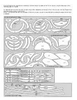
Building the Tail Surfaces
19.
Cover the stabilizer plan with wax paper. Build the stabilizer and elevators over the plan using laser cut parts S-2 and S-3.
Use 3/32" x 1/4", 3/32" x 3/16", and 3/32" sq. for all remaining parts.
20.
Remove the stabilizer and elevators from the plan and sand the edges round and smooth on the entire assembly.
21.
Test fit the stabilizer to the fuselage. Now set the tail surfaces aside until needed for covering.
Building the Wings
22.
Cover the wing plan with wax paper. Pin the 3/32" x 1/4" lower wing spar into position over the plan.
23.
Pin the 3/32" x 1/4" trailing edge into position. Place rib W-1 into position and glue it to the lower spar and trailing edge
while using the dihedral gauge to maintain the proper angle.
24.
Place rib W-3 into position and glue it to the lower spar and trailing edge while using the dihedral gauge to maintain the
proper angle. Now glue rib W-4 and another rib W-3 against the fIrst rib (W-3).
25.
Glue ribs W-2 into position. Use a small square to position these ribs 90 degrees to the building board.
26.
Assemble the wing tip parts W-8,W-9, and W-10.
27.
Glue four small doublers made from 3/32" x 1/4" balsa to rib W-11 as shown on the plan. Trim these doublers flush with the
top and bottom surface of the rib. Drill a 1/32" dia. hole between the doublers to accept the rigging thread during the final
assembly. Now glue rib W-11 into position.
28.
Glue ribs W-5, W-6, and W-7 into position.
29.
Glue leading edge 1/8" sq. balsa into position. Now glue the two leading edge spars 1/16" sq. into position.
30.
Remove the wing panel from the plan and sand smooth all over. Now repeat the proceeding section to build the opposite
wing panel.
31.
Laminate the two landing gear assemblies using parts L-3 through L-4. Sand the wheel faring to a tear drop shape.
32.
Insert L-1 into wheel faring and glue. Sand the leading and trailing edge of the leg round.
Cover the Model
33.
Sand the entire model smooth with 400 grit sandpaper. Test fit the wings to the fuselage. Test the tail surface with the
fuselage. Make any adjustments necessary to achieve the proper fit.
34.
Coat the exposed surfaces with two coats of clear dope.
35.
Attach the tissue to the model with clear dope mixed 50/50 with thinner.