SIG Gee Bee R-2 Assembly Instructions Manual Download Page 3


Beginners Note

 
These instructions were written assuming that the builder has previous building experience. If this is your frrst model then we 
recommend that you purchase a copy of the following book: 
 

Rubber Powered Model Airplanes By: Don Ross


This excellent book covers basic building and flying procedures and provides valuable information about all aspects of building 
and flying rubber powered model airplanes.
 

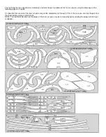
Building the Fuselage

 
1.

 
Pin the fuselage plan to the building board and cover it with wax paper.

 
2.

 
Pin the fuselage keel pieces K-1 through K-6 into position on the plan.

 
3.

 
Laminate parts F-3, F-3A, and F-3B together. Make sure stringer notches are aligned with each other. Be sure to make 
one left hand and one right hand.

 
4.

 
Position F-1 on the front of K-1 and K-6. The top of formers F-1, F-2, F-4, F-5, and F-6 are determined by a "v" notch 
located on the inside of the formers. Use a small square to hold F-1 at a 90 degree angle to the building board. Glue F-1 
into position.

 
5.

 
Carefully glue formers F-2 through F-8 into position on the fuselage keel making sure that they are at 90 degrees to 
building board.

 
6.

 
Position the master stringer F-9 onto the fuselage assembly and make sure that it is pressed in completely before glue is 
applied.

 
7.

 
Glue the 1/16" sq. fuselage stringers into position. Note: Start at the rear of the fuselage and work toward the front.

 
8.

 
Remove the fuselage from the plan. Add the formers to the opposite side of the keel and glue the master stringer into 
position. Now glue the remaining stringers into position.

 
9.

 
Glue pieces F-10, F-11, and F-13 into position. Cut to fit, position, and glue 3/32" x 1/4" balsa for rigging as shown on 
fuselage plan.

 
10.

 
Laminate parts F-12 to F-1. The basic fuselage structure is now finished. Now sand the fuselage smooth all over. Sand 
and round off the F-12's as shown on plan.


Building the Cowl

 
11.

 
Pin C-1's to fuselage plan.

 
12.

 
Glue C-2, C-3, and C-4 to top and bottom C-1's making sure that they are at 90 degrees to the building board.

 
13.

 
Position and glue the main cowling stringer C-1 onto the assembly.

Summary of Contents for Gee Bee R-2

Page 1: ...anual 1 9 Plastic Propeller 1 Propeller Shaft 2 Brass Washer 1 Nylon Propeller Bearing 2 Plastic Wheels 1 3 16 x60 Rubber Strip 9 Laser Cut Sheets Tools and Building Supplies You will need the following items to assemble this model You must read and follow all of the manufactures instructions provided with these items Glue CA White Glue Sigment or Ambroid all work well Cutting Tools A hobby knife ...

Page 2: ...llowing pages as a guide It is possible that several of the laser cut parts may not be completely cut through If this is the case you can free the part from the sheet quickly using an X acto knife NOTE The slight discoloration on the edges of the laser cut parts may be removed by lightly sanding the edges with 400 grit sandpaper ...

Page 3: ... angle to the building board Glue F 1 into position 5 Carefully glue formers F 2 through F 8 into position on the fuselage keel making sure that they are at 90 degrees to building board 6 Position the master stringer F 9 onto the fuselage assembly and make sure that it is pressed in completely before glue is applied 7 Glue the 1 16 sq fuselage stringers into position Note Start at the rear of the ...

Page 4: ...er angle 24 Place rib W 3 into position and glue it to the lower spar and trailing edge while using the dihedral gauge to maintain the proper angle Now glue rib W 4 and another rib W 3 against the fIrst rib W 3 25 Glue ribs W 2 into position Use a small square to position these ribs 90 degrees to the building board 26 Assemble the wing tip parts W 8 W 9 and W 10 27 Glue four small doublers made fr...

Page 5: ...ion on the fuselage 49 Assemble the propeller shaft and bearing with laminate pieces NB 1 3 4 dia NB 2 3 4 sq and NB 3 5 8 sq Paint this assembly black Tie the rubber motor Install the prop and motor using the 3 32 dowel to retain the motor at the aft end of the model 50 Balance the model at the points shown on the plan Add weight to the nose or tail as required to achieve the proper balance 51 Yo...

Page 6: ... damaged buy use or modification In no case shall Herr Engineering Corporation s liability exceed the original cost of the purchased kit Further Herr Engineering Corp reserves the right to change or modify this warranty without notice In that Herr Engineering Corporation has no control over the assembly or use no liability shall be assumed or accepted for any damage resulting from the use by the u...

Reviews: