


.
53.
a. Remove the wing and tap the wing hold-down blocks with a 1/4-20 tap.
Apply a few drops of thin CA to the holes to strengthen the threads. When
you are absolutely certain that the CA has cured, clean up the threads by
re-tapping the holes.
b. Redrill the holes in the wing with a 1/4" drill bit to pass the nylon wing
bolts.
Servo And Pushrod Installation
54.
The servos need to be mounted in the fuselage so that the nylon push rods can be routed properly, with the least amount
of curvature. Refer to Chapter 2 of "The Basics of Radio Control" and the plans for information on where and how to mount
the servos in the fuselage. Start by cutting two 4-1/4" long servo rails from the supplied 3/8" sq. basswood stick. The ends
of the servo rails searin the die-cut lite-ply servo rail supports (SRS), which in turn slide against the "flat" inner edge of the
fuselage doubler. Use your servos (or servo tray if you plan on using one) to properly space the servo rails. When satisfied
with their position, glue the servo rails and servo rail supports in place.
55.
a. Lock the rails in place by gluing a scrap piece of lite-ply or balsa at each
end of both rails.
b. Mount your rudder, elevator, and throttle servos to the rails.
56.
a. Locate the two .270 o.d. x36" nylon outer pushrod tubes (black), and
roughen the last 4" of each with sandpaper to aid glue adhesion.
b. Slide the outer pushrod tubes forward through the pushrod exit slots in the
fuselage sides and the notches in F-6. Continue sliding the tubes until
only about an inch sticks out past the slots.
c. The outer pushrod tubes should nearly meet (but not cross) at the notch in
F-5. Glue a scrap of balsa below the tubes to hold them in place.
d. Apply glue (either slow CA or epoxy) to the outer tubes at the push rod
exit slots, from both the inside and the outside of the fuselage.
e. Use a single-edge razor blade to trim the outer pushrod tubing flush with
the outside surface of the fuselage.
57.
a. The nylon push rods must be supported at each former to keep them from
flexing under load. Use the die-cut lite-ply pushrod straps, F-3S and F-4S,
to support the push rods. Notice that the pushrod straps haven't been
marked for push rod location because the routing of the pushrods will vary
with different servo installations. Ideally, you want to have the push rods
to come through F-3S pointed directly at fhe servo arms of the rudder and
elevator servos. Carefully mark the pushrod locations on the plywood
straps, then drill at the marks with a 9/32" drill bit.
b. Cut off the front ends of the outer push rod tubes about an inch forward of
F-3. Slide F-4S then F-3S into position on the push rods, but don't glue
them in yet.
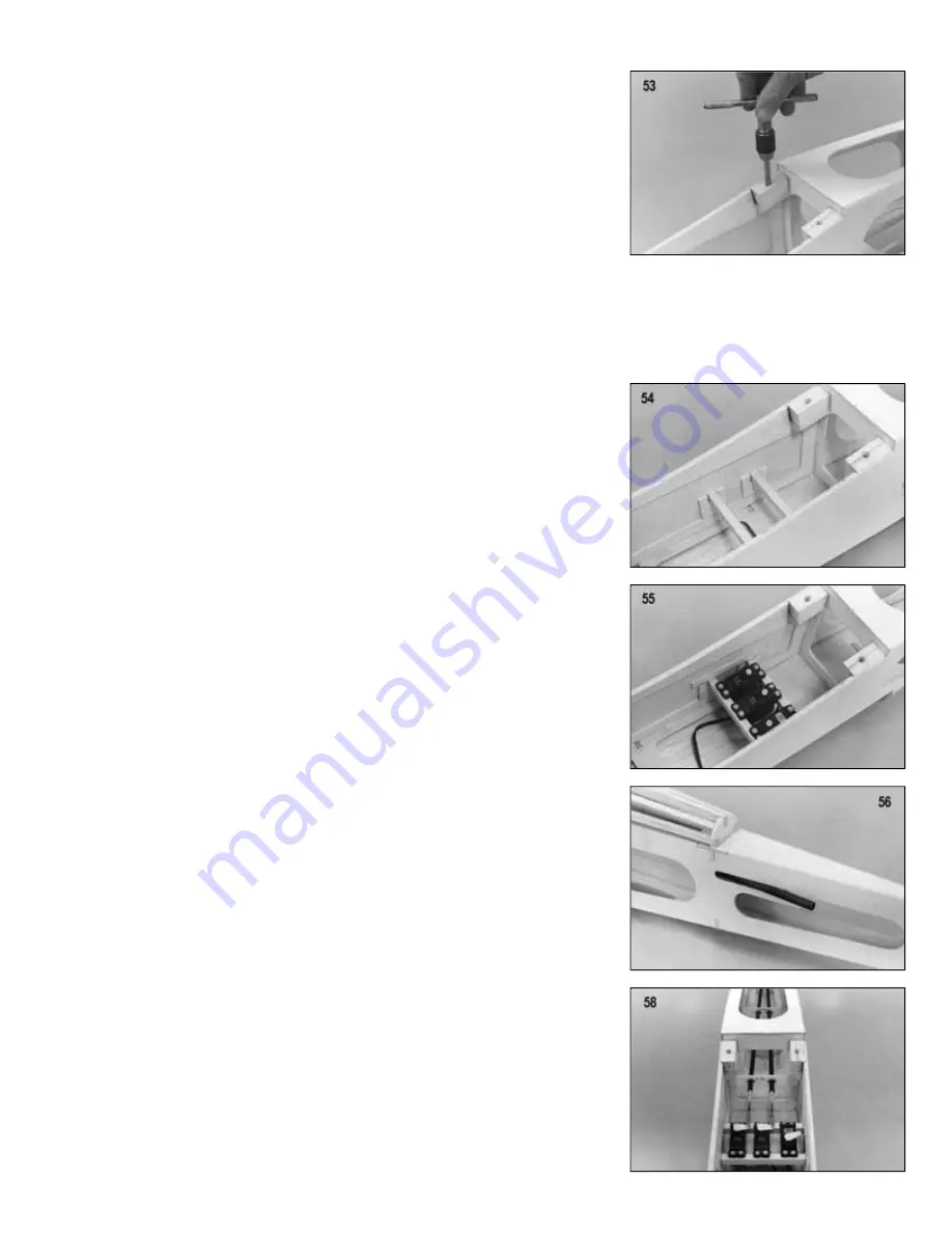
58.
a. Cut two 4-40 x 8" threaded rods to an overall length that is equal to the
distance from your servo arm to the end of the black tube (this distance
will vary depending on your servo placement). Solder a 4-40 solder clevis
to the smooth end of each rod.
b. Screw the threaded end of the rods completely into the two .200 o.d. x36"
nylon inner pushrod tubes (yellow).
c. Slide the inner pushrod tubes into the outer tubes from the servo end.
Attach the solder clevises to the servo arms and hook them up to the
servos.
d. With the push rods hooked up to the servos, you can now glue F-3S and
F-4S to the front of F-3 and F-4, respectively, in such a way as to keep the
bends in the push rods to a minimum.
Summary of Contents for Four-Star 120
Page 29: ... ...