SIG Antoinette 1909 Manual Download Page 20

When dry, reinforce the seams by applying a little Thick CA glue on the inside of the cylinders. Let dry.

84d.

 
Carefully drag the bottom of the cylinder bank against a fine sanding block (150 
grit or finer) to even out the edges. Don’t try to sand too fast or too hard. You’ll 
crush the thin plastic. Just drag the part lightly back and forth across the block 
and let the sandpaper do the work.


e.

 
The excess flange around the outside of each cylinder bank can now be carefully 
trimmed and sanded to final shape. Use 220 grit sandpaper and/or small 
jeweler’s files. Do not attempt to eliminate the seam completely, but rather work 
to make it as uniform as possible for a good appearance. When the engine is 
painted, the seam lines become very muted and won’t detract from the scale 
appearance.

 
85.

 
If you intend to paint your cylinders a different color than the crankcase, like we 
did ("steel" for the crankcase, "copper" for the cylinders), then you should paint 
them now. Allow the paint to dry before continuing.
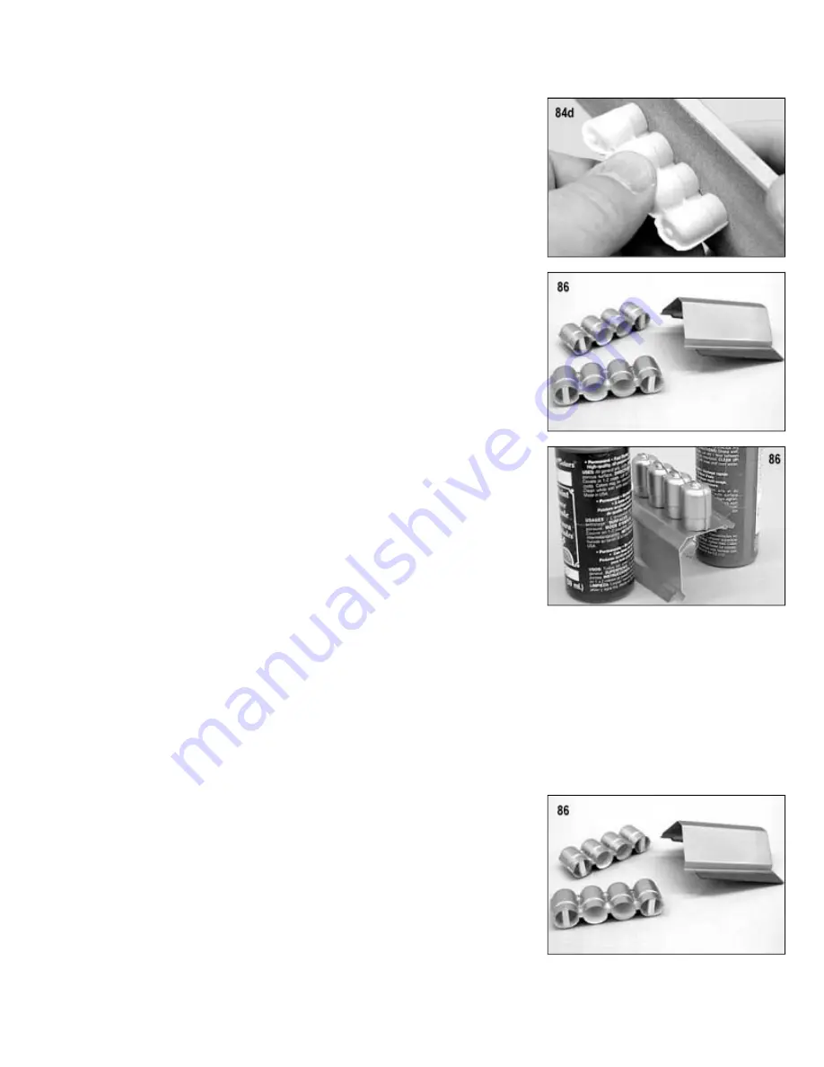
86a.

 
Cut four 1/2" long pieces of 1/8" sq. scrap balsa stick. Adjust the length of the 
sticks as needed to fit inside the bottom of both end cylinders of each cylinder 
bank. Glue the sticks in flush with the bottom edge of the plastic cylinder. These 
sticks provide more gluing surface for attaching the cylinder banks to the 
crankcase in the next step.

b.

 
Put a drop of Medium CA on the balsa gluing sticks and then, carefully set the 
cylinder bank in place on the side of the crankcase. Prop the assembly up so the 
cylinder bank won’t fall off and leave it alone to dry.

Note: We don’t use CA Accelerator during this installation because it can mar the 
metallic paints we used on the cylinders and crankcase. Most brands of Medium 
CA will dry on its own, without accelerator, in 15-20 minutes.

c.

 
When dry, glue the second cylinder bank in place on the other side of the 
crankcase. Let dry.

 
87.

 
The dummy engine assembly, as provided in the kit, is now basically complete. For some modelers, this may be enough 
and they will want to move on. However, there are always those who want a little more "eye candy" and will want to fully 
detail the engines. For these folks, we'll share some additional detailing tips that we used on our dummy engines 
(materials for these additional details is not provided).
 
As mentioned earlier in the PAINT section of this manual, we used a selection of flat Testor's Model Master™ plastic 
model paints - both spray can and brushable types - for painting and detailing the dummy engine. The plastic crankcase 
was sprayed with Steel. The cylinders were sprayed with Copper. We made the exhaust pipes out of 1/8" od K&S™ 
Aluminum Tubing, carefully bent to shape, and then, painted with Burnt Metal Buffing Metalizer™. Thin or medium CA glue 
was used to attach the finished exhaust pipes to the cylinders.
 
The "sparkplugs" were made from 1/32" K&S™ Aluminum Tubing. Spray or brush 
the tubing with Flat White or Flat White Primer and allow to dry. Cut 1/4" lengths 
of the painted tubing for the sparkplug bodies. Cut 3/8" lengths of .031 music wire 
for the sparkplug tips. Glue one of the music wire pieces into each sparkplug 
body, leaving 1/8" of wire exposed. Use medium CA glue to install the spark 
plugs into pre-drilled holes in the top of each cylinder head. Use a 1/2" long piece 
of leftover 1/4" balsa dowel to simulate a distributor on the back end of the 
crankcase. 
The sparkplug wires are made from thin black or gray R/C hook-up or antenna 
wire. Cut the 8 sparkplug wires to length, plus an extra inch on each one to work 
with.


Use a pliers to pull the metal wire out of the plastic insulation. One end of the plug wire is placed over the wire tip of each 
sparkplug (warming the tubing with a little heat relaxes it enough to do this). The other end of the tube is inserted into a 
distributor. Done neatly, the overall effect can be very convincing!

Summary of Contents for Antoinette 1909

Page 1: ...ngine specifically for the new sport of motor boating Named for Gastambide s daughter Antoinette the engine was a large success and by 1904 it was powering winning powerboat racers all over Europe By 1906 in response to the rapidly growing interest in aviation a new company was formed for the commercial development and production of the Antoinette engine for use in aircraft Gastambide was the pres...

Page 2: ...lly looks the part in the air The airplane is capable of extremely slow flight and is likely very close to scale speeds When built to these instructions and properly detailed the SIG indoor R C Antoinette is very believable on the ground or in the air Building your Antoinette has been made easy with the supplied laser cut parts The included profile pilot has been used in all of our Antoinette mode...

Page 3: ...ape four cells on the bottom three cells on top This layout offers the most mass in the least amount of space and this is very helpful when making small changes in the C G location if needed For maximum flight performance indoor R C models require attention to the weight of everything they must carry aloft including connectors We used and liked the small 2 prong Dean s connectors for connecting th...

Page 4: ...ne crankcase was sprayed Steel color The cylinders are Copper just like the real Antoinette engine had The exhaust pipes look good painted with Exhaust Buffing Metalizer The dummy gas tank looks great painted Copper just like on the full scale Antoinette COMPLETE KIT PARTS LIST Balsa Sticks Sheets 1 1 16 x1 4 x24 Balsa Sticks for W1 Rib Stiffeners 3 1 8 x1 8 x43 Balsa Sticks for Fuselage Longerons...

Page 5: ... ...

Page 6: ... in order to make the most efficient use of the stock 36 long sticks This is good advice for this step and throughout the entire construction of this airplane 4 Glue formers F2 F3 F4 F5 F6 F7 F8 F9 F10 F11 F12 and F13 in place Make sure all these formers are glued in perpendicular 90 deg to the building board Do not install former F1 at this time or the 1 8 sq balsa doublers that go between F1 and...

Page 7: ...hen trial fit the Tail Skid on the bottom of the fuselage You could glue it on now which would lend support to the rudder post but we ve found it s a lot easier to cover the rear of the fuselage without the Tail Skid in place So set it aside for now and try to be careful not to break off the rudder post 11 Double check that the ends of the two 1 8 sq balsa Top Longerons are cut off right at the fr...

Page 8: ...eron between formers F1 F2 21 Glue the laser cut rear dihedral brace RDB in place on the rear of former F6 Study the plans including the F6 cross section drawing to make sure you understand exactly where it goes It should sit perfectly between the fuselage side sheeting right up against the back of F6 22 Trial fit the laser cut receiver mount RXM in place at the front of former F6 Bevel the outsid...

Page 9: ...continue gluing along the spokes and hub areas NOTE It s best to use a fine applicator tip on your CA bottle during assembly of these wheels In fact a fine tip is preferred for the assembly of this entire kit Building featherlight models like the Antoinette requires that we change our thinking a bit from the old habits we ve used in building much heavier sport type models With the small parts invo...

Page 10: ...p Press a 046 dia x1 1 2 straight music wire Axle into each hole Leave about 9 16 of the Axle wire sticking out of the end of the Spreader Make sure the Axle comes out straight and parallel to the Spreader Then flow Thin CA glue around the wire It will soak into the balsa Spreader gluing the wire permanently in place Let dry 36 Place the wheels on the axles and double check that they rotate freely...

Page 11: ...at each dowel has a 6 1 8 long slot in one end Glue a 1 32 plywood WSF wing stiffener in each slot with thin CA Make sure the edges of the WSF plywood do not protrude outside the diameter of the dowel When dry sand very lightly to smooth out any rough spots Then trial fit the stiffened end of the dowel inside one of the 1 4 id aluminum wing mount tubes If the dowel is too big gradually sand it dow...

Page 12: ...cisely on the outside of the fuselage by pushing a pin thru side sheeting from the inside Then mark and cut the 3 8 dia hole from that point Also due to the fragile nature of the side sheeting it s best to make the hole undersize first and then gradually open it up closer to finished size Finish shaping and sizing the hole with sandpaper wrapped around a scap of 1 4 dowel 52 Sand the outside of th...

Page 13: ... from the plan and lightly sand all the glue joints smooth Note Remember to cut the longest pieces of 1 8 sq balsa first then the shorter pieces in order to make the most efficient use of the stock 36 long sticks 56 Use 1 8 square balsa sticks and laser cut part CHG to construct the Elevator directly over the drawing When dry unpin the Elevator from the plan and lightly sand all the glue joints sm...

Page 14: ...covering to stick with the heat activated adhesive following the manufacturer s instructions On both wing panels apply adhesive to the leading and trailing edges the tip and root ribs and to the top surface of each wing rib Allow the adhesive to dry to the touch Pre Shrinking Litespan is capable of shrinking a great deal We have tried several methods to control this tendency including pre shrinkin...

Page 15: ...stabilizer Sight straight down the trailing edge of the Fin to make sure that it lines up with the fuselage tail post underneath the stabilizer 62 Built into the front of both the rudder and elevator is a balsa control horn gusset CHG Cut away the covering material over the small slit in CHG Insert a laser cut plywood control horn CHN into the slit center the horn and then glue with Thin CA 63 A s...

Page 16: ...with the servo Be sure to drill pilot holes in the mounts so the screws won t split the wood 68 Set the rudder servo minus the control arm in place in the fuselage Check the fore and aft positioning of the servo in comparison to the side view plan The output shaft of the servo should be 2 1 8 ahead of former F7 Also check to see that the servo sits far enough down in the fuselage If you made your ...

Page 17: ...ion Then adjust the rudder to neutral position by sliding the monofilament line through the servo arm lengthening one side while you shorten the other side at the same time When you have the rudder properly neutralized secure the pull pull line by placing a single small drop of glue on the line where it passes through one of the holes in the servo output arm NOTE In all the hours of indoor flying ...

Page 18: ...aside these parts for re assembly later 76 With a small Phillips screwdriver remove the four screws from the front of the motor s plastic gearbox Also remove the two smaller screws that hold the motor to the front of the plastic gearbox Then separate the front of the plastic gearbox from the rest of the motor unit 77 Set the front of the plastic gearbox in the cutout in the plywood Motor Mount it ...

Page 19: ...The back end of the crankcase the end with the sharper corners goes right along the back edge of the Dummy Engine Base c Mark and then cut off the front end of the Crankcase vertically 2 9 16 from the back end d Trim out the bottom 1 4 of the back end of the crankcase so that it will clear the battery pack 83a Bend ENGINE HOOK 1 and ENGINE HOOK 2 out of 020 dia music wire according to the full siz...

Page 20: ...nder bank in place on the other side of the crankcase Let dry 87 The dummy engine assembly as provided in the kit is now basically complete For some modelers this may be enough and they will want to move on However there are always those who want a little more eye candy and will want to fully detail the engines For these folks we ll share some additional detailing tips that we used on our dummy en...

Page 21: ...Use a piece of light 1 32 balsa sheet cut to 1 1 2 long Roll the balsa sheet tightly around the tube until you have the edges overlapped Secure it tightly with a piece of tape With a straightedge and sharp hobby knife cut away the excess balsa to create a tight seam between the edges of the sheet c Slip a 3 or so length of waxed paper between the balsa sheet and the tube beneath the seam Hold the ...

Page 22: ...be a little resistance as the Screw Checker starts to shave off the corners of the balsa stick Turn the stick around and push it through the hole again in the opposite direction Continue passing the stick through the 6 32 hole until no resistance is felt d Next push the balsa stick through the 5 40 threaded hole in the Screw Checker This will be pretty snug the first time through Turn the stick ar...

Page 23: ...s until there is an equal amount of post above and below the wing rib Align the posts by eyeball sighting from the root end of the wing making sure the posts are parallel to each other and that they are perpendicular to the chord line of the airfoil Also make sure that the holes in the ends of the posts are running span wise to the wing When satisfactory glue the Wing Rigging Posts to the side of ...

Page 24: ...in the bottom of the rear Wing Rigging Post and then back to point A 100 Repeat step 97 to install a 28 length unstretched of elastic thread from point F through hole HT in the top of the front Wing Rigging Post then through the tube at rigging point J through hole HB in the bottom of the front Wing Rigging Post and then back to point F 101 Repeat steps 97 through 100 to install the same rigging w...

Page 25: ... on the landing gear None of these rigging wires needs to be removable The ends are simply spot glued with a tiny drop of Thin CA onto the model structure as outlined in the following steps 107aThe first 7 long piece of elastic thread runs from point P on the axle through the hole at point M and ends at point Q on the axle Start by placing a tiny drop of Thin CA on one end of the elastic thread Qu...

Page 26: ...ilot 111 Cut the parts of the printed cardboard pilot from the sheet with a sharp 11 hobby knife or scissors Cut as accurately and close to the image as possible 112 Drill a 1 16 dia hole in the shoulder areas of the arms and body of the pilot The locations for the holes are marked by a black dot 113 Assemble the arms to the body using the 00 90 x1 8 long brass bolts hex nuts and washers that are ...

Page 27: ... the ceiling height permits take the airplane up higher using throttle to seek and then hold any given altitude This is a good exercise in learning how to fly this model It won t be long before you re perfectly comfortable with this very nice flying scale model Make a few low slow passes and listen to your flying buddy s comments When you re ready to land remember the landing technique that you pr...

Page 28: ...hat the Antoinette and many other early pioneer aeroplanes actually looked like in flight It s fun to watch while you re building your own Antoinette Good luck and safe flying Hubert Latham and his record setting Antoinettes 1909 1910 Antoinette replica built for the movie Those Magnificent Man and Their Flying Machines Customer Service SIG MFG CO INC is totally committed to your success in both a...

Page 29: ... safe manner The first test flights should only be made by an experienced R C flyer familiar with high performance R C aircraft The governing body for radio control model airplanes in the United States is the ACADEMY OF MODEL AERONAUTICS commonly called the AMA The AMA SAFETY CODE provides guidelines for the safe operation of R C model airplanes While AMA membership is not necessarily mandatory it...

Page 30: ...s model airplane kit will ultimately determine the airworthiness flight performance and safety of the finished model SIG MFG CO s obligation shall be to replace those parts of the kit proven to be defective or missing The user shall determine the suitability of the product for his or her intended use and shall assume all risk and liability in connection therewith ...

Reviews: