


Whatever brand engine you choose, take the time to carefully
break it in according to the manufacturer's instructions. A good
running, reliable engine is a minimum requirement for the enjoy-
ment of this or any R/C model aircraft.
❑
PROPELLER FOR GLOW
Refer to the engine manufacturer’s instructions for recommenda-
tions on proper propeller size for their engine. In our experience,
most 2-stroke .60-.75 glow engines will fly the 4-STAR 64 very
nicely with a 12x8 or 13-6 prop.
FOR ELECTRIC POWER
❑
1200 - 1700 watt BRUSHLESS OUTRUNNER MOTOR
The 4-STAR 64 is designed to be powered with a 1200 to 1700
watt electric brushless outrunner motor. This size motor is some-
times referred to as a "60" class motor to those who like to make
a comparison to a glow motor. Also, the motor you choose should
be rated at 400-600 kv, in order to turn an appropriate propeller.
Here is are some motor sizes that work well in the 4-STAR 64:
5030-390
5062-400
5055-650
5065-400
❑
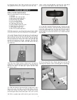
MOTOR MOUNT
A laser-cut plywood adjustable motor mount is included in this kit.
It should work perfectly for any suitable brushless outrunner motor
which has an “X” or “cross” motor mount plate on the back.
❑
75 amp ESC (Electronic Speed Control)
We use the Castle Creations 75 ESC in all our 4-STAR 64 proto-
types. This is an excellent "switching type" ESC that has a built-in
5amp BEC that is safe to use with a 4 or 6 cell lipo battery pack.
We typically see amp draw of 35 to 48 amps, depending on
whether a 4 or 6 cell lipo is being used, and the propeller size.
Important Note: BEC (Battery Eliminator Circuit) allows you to
use the same battery pack to power both your motor and your
radio system, eliminating the normal radio battery pack. When
the single battery pack runs down in flight to a prescribed point,
the BEC circuit in the ESC will shut down the motor and leave
enough power to operate the radio while you land the model. Note
that the BEC feature in some cheaper ESCs does not work with
4 cell and larger lipo battery packs - only 3 cell packs. Check the
manual of your particular ESC to learn if this is true in your case.
If your BEC is not rated for your battery choice you have three op-
INTRODUCTION
Congratulations on your purchase of the SIG 4-STAR 64 EG ARF.
We hope you will enjoy this unique fun scale R/C model.
Assembly of your 4-STAR 64 EG ARF is fast and simple when
following the detailed instructions in this manual. We urge you to
read this assembly manual completely before assembly. Famil-
iarize yourself with the parts and the assembly sequences. The
successful assembly and flying of this airplane is your responsi-
bility. If you deviate from these instructions, you may wind-up with
problems later on.
Good luck with the 4-STAR. Let’s get started!
ADDITIONAL ITEMS YOU WILL NEED TO PURCHASE
In addition to this kit, you will need the following items to complete
your 4-STAR 64 and make it flyable.
❑
RADIO SYSTEM
The Four Star 64 EG requires a standard 4-channel radio system
and four to five standard size servos (number of servos depends
on whether you are using glow or electric power). In addition,
you'll need two 12"- 24” long Servo Extension Chords (actual
length needed will depend on how long the wires are coming off
your servos – plan accordingly), and one Y-Harness Chord for
connection of the two aileron servos to the receiver.
POWER SYSTEM - GLOW OR ELECTRIC?
The biggest decision you will have to make is whether to power
your 4-STAR 64 with a glow engine (2-stroke or 4-stroke) or an
electric motor. We have flown the 4-STAR 64 on a variety of both
types of power systems, and we make the following recommen-
dations based on our successful on-field experience.
FOR GLOW POWER
❑
ENGINE
We recommend the following size engines for the 4-STAR 64.
2-STROKE - .60 to .75 cu. in.
4-STROKE - .60 to .90 cu. in.
2
What do those numbers mean?
NOTE: This numbering system is very common, however there
are exceptions. For instance, some motor manufacturers will
list the actual diameter of the stator (armature) inside the motor
instead of the case diameter. Some may list the length of the
stator inside the motor instead of the case length. Some will
give you both if you dig far enough into their specs. Make sure
you understand the motor manufacturer’s numbering system
when shopping for a motor.