


41110555
Rev 1.0
November 01, 2017
30
Product Technical Specification
Detailed Interface Specifications
VBATT
VGPIO ( pin 45 )
PWR_ON_N
Power OFF
Power ON
Power OFF
Base Band
PMU supply
Module is
OFF
Module is
OFF
Module is
ON
RESET
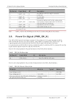
Figure 6.
PWR_ON_N and PWR_OFF Sequence
Note:
As PWR_ON_N is internally pulled up with 1MΩ, an open collector or open drain transistor must be
used for ignition.
VGPIO is an output from the module that can be used to check if the module is active.
•
When VGPIO = 0V, the module is OFF
•
When VGPIO = 1.8V, the module is ON (it can be in idle, communication or sleep mode)
Note:
To power the module off, use AT command
AT+CPOF
or
AT+CPWROFF
.
3.10. Reset Signal (RESET_IN_N)
To reset the module, a low-level pulse must be sent on the RESET_IN_N pad for 20ms (TBC). This
action will immediately restart the AirPrime HL77xx module with the PWR_ON_N signal at low level. (If
the PWR_ON_N signal is at high level, the module will be powered off.) As RESET_IN_N is internally
pulled up, an open collector or open drain transistor should be used to control this signal.
Note:
As RESET_IN_N is referenced to the VGPIO signal (1kΩ pull-up resistor to VGPIO 1.8V) an open
collector or open drain transistor should be used to control this signal.
Refer to the following table for the pad description of the RESET_IN_N interface.
Table 22. RESET_IN_N Pad Description
Pad Number
Signal Name
I/O
Description
12
RESET_IN_N
I
Hardware reset the module


