


41110555
Rev 1.0
November 01, 2017
29
Product Technical Specification
Detailed Interface Specifications
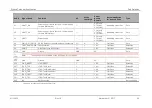
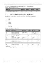
Pad Number Signal Name*
I/O*
Description
4
UART1_CTS
O
The AirPrime HL77xx is ready to receive AT
commands
5
UART1_TX
I
Transmit data
6
UART1_RX
O
Receive data
7
UART1_DTR
I (active low)
Prevents the AirPrime HL77xx from entering sleep
mode, switches between data mode and command
mode, and wakes the module up.
8
UART1_DCD
O
Signal data connection in progress
9
UART1_DSR
O
Signal UART interface is ON
*
According to PC view.
Note:
UART1_CTS must be left floating or set to level “0” before starting the HL77xx module.
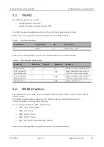
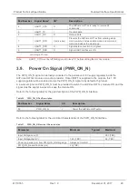
3.9. Power On Signal (PWR_ON_N)
The PWR_ON_N signal is internally connected to the permanent 1.8V supply regulator inside the
AirPrime HL77xx module via a pull-up resistor. Once VBATT is supplied to the module, this 1.8V
supply regulator will be enabled and so the PWR_ON_N signal is by default at high level.
A low-level signal on PWR_ON_N must be provided to switch the AirPrime HL77xx module ON, and the
signal must be kept at low level to keep the module ON.
Refer to the following table for the pad description of the PWR_ON_N interface.
Table 20. PWR_ON_N Pad Description
Pad Number
Signal Name
I/O
Description
59
PWR_ON_N
I
Power the AirPrime HL77xx On
Refer to the following table for the electrical characteristics of the PWR_ON_N interface.
Table 21. PWR_ON_N Electrical Characteristics
Parameter
Minimum
Typical
Maximum
Input Voltage-Low (V)
-
0.51 (TBC)
Input Voltage-High (V)
1.33 (TBC)
-
2.2 (TBC)
Power-up period (ms) from PWR_ON_N falling edge Always set to GND
-
-
PWR_ON_N assertion time (ms)
25 (TBC)


