


PinPoint X 1x/EV-DO
44
20070914
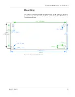
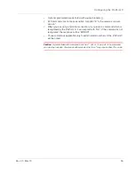
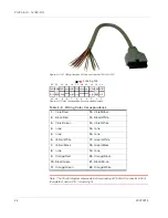
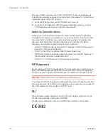
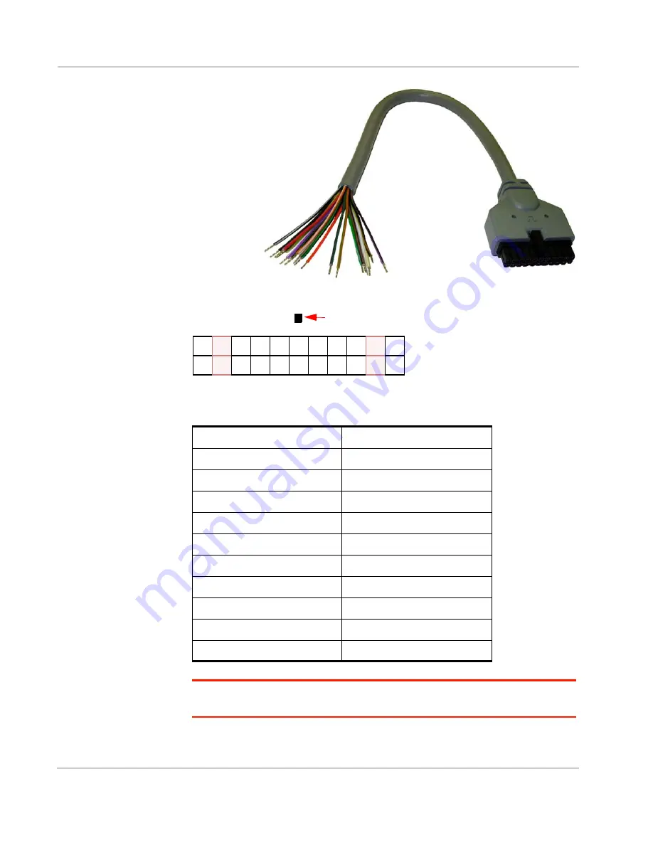
Figure 6-4: I/O Wiring Harness, AirLink part number 120-140-1014
Figure 6-5: Color Corospondance to connection points
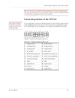
Note: The Pin-Out diagram shows external view looking at PinPoint X connector in front
face-plate of device. Pin 1 is lower right.
Table 6-2: Wiring Color Corospondance
1.
Violet/Red
12.
Violet/Black
2.
Black/Red
13.
Black/White
3.
Violet/Green
14.
Violet/White
4.
none
15.
none
5.
none
16.
none
6.
Yellow/White
17.
Green/White
7.
Yellow/Black
18.
Green/Black
8.
none
19.
none
9.
Orange/Red
20.
Orange/Black
10.
Black/Green
21.
Black/Brown
11.
Orange/Green
22.
Orange/White
1
2
3
4
5
6
7
8
9
10
11
12
13
14
15
16
17
18
19
20
21
22
none
none
none
none
O/W
V/R
V/Bl
Bl/R
Bl/W
V/G
V/W
Y/W
G/W
Y/Bl
G/Bl
O/R none
none
O/Bl
Bl/G
Bl/Br
O/G
Locking Tab
Summary of Contents for AirLink PinPoint X
Page 2: ...PinPoint X for Verizon User Guide 20070914 Rev 2 0...
Page 3: ......
Page 7: ...PinPoint X 1x EV DO iv 20070914...
Page 11: ...PinPoint X 1x EV DO viii 20070914...
Page 21: ...PinPoint X 1x EV DO 10 20070914...
Page 45: ...PinPoint X 1x EV DO 34 20070914...
Page 51: ...PinPoint X 1x EV DO 40 20070914...
Page 61: ...PinPoint X 1x EV DO 50 20070914...
Page 62: ......


