background image

Page 

23


Document Number: 0072 


Rev. 09


CONTROLLED COPY 

10.  INSTALLATION 

10.1  CONNECTOR & PENETRATOR INSTALLATION 

It is recommended that the installation of all SpecTRON Penetrators and Mounted Connectors is 
undertaken by Siemens Subsea site engineers or trained personnel. 
 

10.2  HOSE COMPENSATION 

The hose within a pressure balanced oil filled (PBOF) jumper performs two functions: 
mechanical protection to the cables inside and forming a primary barrier between the 
electrical insulation and seawater. The cable is not fixed and can move within the hose volume, 
testing by Siemens Energy has shown that the three conductors lay next to each other at the bottom 
of the hose in direct contact with the hose inside diameter. 
The oil volume within a hose is compensated through changes in the cross-sectional profile of the 
hose. 

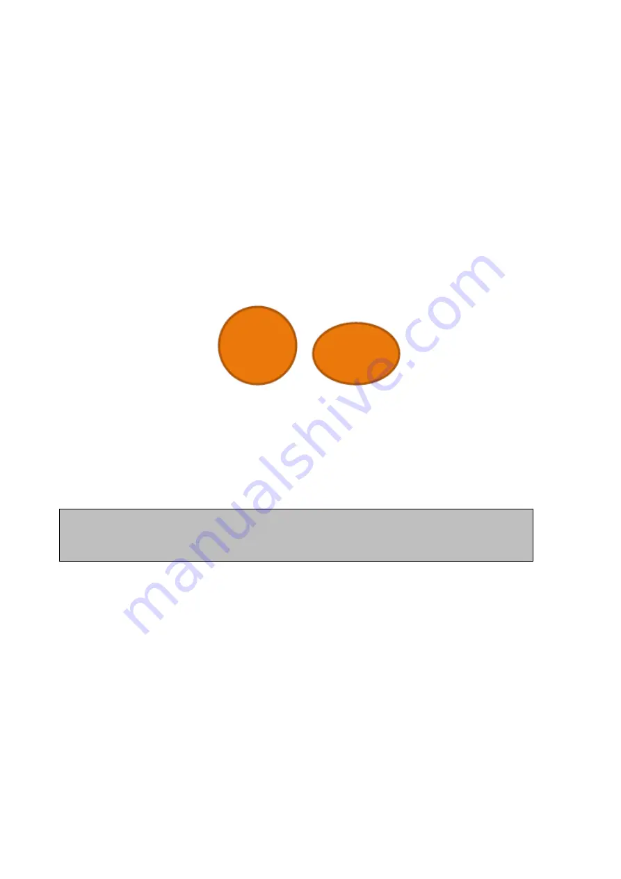
Figure 17

  - Hose Profile, (left to right), as filled, and when compensating


AquaTRON 200 harnesses (Orange Hose) are provided from factory with a 10bar internal 
overpressure, however due to the flexible nature of the materials involved it is possible that some 
over pressure may be lost during shipping and storage. This is dependant on a no. of factors 
including length and temperature. However a positive pressure will always be maintained and no 
flattening of hose should be observable topside. 


Once deployed a certain amount of flattening is expected (dependant on deployment depth), this is 
an ordinary occurrence related to the compensation system of the harness. Harness is designed to 
equalise the pressure between the external seawater depth pressure and the internal oil filled hose.  
 
The amount of compression is directly related to depth pressure, but all depth extremes have been 
considered. As long as harness is routed to MBR there shall be no adverse effects to electrical 
conductors within hose (see section 10.3 for guidance on routing). 
 
Should any kinking (abrupt change in direction below MBR) of the hose be observed, the harness 
should be re-routed/deployed to try and remove the feature. If this continues it could indicate a lack 
of internal pressure. In which case the harness should be recovered for further inspection topside, 
including: 
 

  Thorough visual inspection of the retrieved jumper for damage and correct 

shape, indicating the hose pre-charge pressure remains acceptable. 

  Insulation resistance measurement to validate the electrical performance of the jumper.  


Note:


1.5” Gorilla Harnesses (Yellow Hose) are not provided with an internal over 

pressure, this is not required at their rated depth of deployment. However the guidance 
below should still be followed. 
 

Summary of Contents for SpecTRON 5

Page 1: ......

Page 2: ...ON naming convention corrected throughout the procedure Note added to 4 2 Project Specific Connector storage Temperature may vary 24 11 11 P Edmondson S Spencer Rev 2 Added section 2 Specification Added section 3 Marking Added section 4 1 Lifting of Jumpers Connectors Added section 5 1 Protective caps Section 7 1 4 Replaced SpecTRON 10 cleaning figure with SpecTRON 5 connectors Made procedure gene...

Page 3: ...s to the routing of hose Section 10 2 1 formers added as recommended designs for formers Sections 10 2 2 added to define routing of hoses in fix installations Section 10 2 3 added to define routing of hoses in dynamic installations 17 12 15 J Keith M Earnshaw Rev 8 Section 3 3 added info on hose MBRs and max allowable hose twist Sections 5 and 8 1 5 amended wording regarding Super Duplex Connector...

Page 4: ...ONNECTORS 8 6 UNPACKING 10 6 1 PROTECTIVE CAPS 10 7 STORAGE 12 7 1 SHORT TERM STORAGE 12 7 2 LONG TERM STORAGE 12 8 DEPLOYMENT MAINTENANCE 13 8 1 SpecTRON 5 13 9 MANUALLY MATING DE MATING ROV CONNECTORS 20 9 1 MATING PROCEDURE 20 9 2 DE MATING PROCEDURE 22 10 INSTALLATION 23 10 1 CONNECTOR PENETRATOR INSTALLATION 23 10 2 HOSE COMPENSATION 23 10 3 HOSE MANAGEMENT ROUTING AND SUPPORT 24 11 INFORMATI...

Page 5: ...for the task safe lifting guidelines must be followed e g adopt correct posture consider team lifting employ safe lifting technique etc Only competent persons are permitted to perform tasks without supervision if in doubt ask Good Housekeeping avoids Slips Trips and Falls keep your area clean and tidy It is the operator s responsibility to comply with current Company regional health and safety leg...

Page 6: ...Deployment Rate 20bar min Max Water Depth 1330 m 3 3 HOSE CABLE 3 3 1 AquaTRON 200 2 bore Outside Diameter 66 mm Minimum Bend Radius dynamic 375 mm Minimum Bend Radius static 375 mm Weight in Air Inc cable and oil 4 3 kg m Weight in Water Inc cable and oil 0 79 kg m Storage Temperature 40 C to 70 C Max allowable hose twist lengths 5m only 180 spread over a length of hose 5m long 3 3 2 Gorilla 1 5 ...

Page 7: ...ally by laser etching Harnesses are also marked with the Siemens Subsea part number and unique serial number for the harness as shown in Figure 2 Client and project specific information is also usually added to these labels Labels are typically black text on a yellow background underneath clear heatshrink Typically labels are located at each end of the harness and also centrally Figure 1 Marking o...

Page 8: ...mage during transit If large numbers are shipped in one consignment a suitably reinforced box will be necessary to withstand the weight Protection caps must be fitted at all times during transport If storage is carried out in saline conditions e g on a ship s deck or hold then full dummy connectors should be used Bulkhead type connectors with exposed tailing wires should be packed and shipped in a...

Page 9: ...Figure 5 The centre of gravity for the Connector or Penetrator is usually marked on the outline drawing supplied in documentation pack but must be verified at low level before commencing any lift For SPO or API flange penetrators lifting eye mounting holes are provided on the flange at 12 and 6 o clock positions ROV Receptacle ROV Plug Figure 4 Recommended lift positions Plug Receptacle Sling arou...

Page 10: ...ESSARY STRAIN ON THE CONNECTOR INTERNALS AND MAY RESULT IN LOSS OF CONTINUITY On harnesses the cable or hose should be supported during lifts to minimise strain on the Connector Penetrator The maximum recommended length of hose which can be unsupported during a lifting operation is 5 meters Protective caps should remain on wherever possible during lifting operations to minimise the risk of damage ...

Page 11: ...on caps Dust caps typically yellow in colour can be simply removed by twisting or pulling them off Protective caps and IP caps typically black in colour can be removed as detailed below 6 1 1 ROV Plug Cap The ROV Plug cap is latched onto the Plug connector via the connector latching mechanism In order to remove the cap it is recommended that the operator stand the Plug vertically on the cap stand ...

Page 12: ...g the termination of the Penetrator to the module It is recommended that only trained personnel remove Penetrator caps though details are provided here for information only Penetrators may be supplied with pre terminated tails which are sealed with a cable gland This should be slackened off prior to removal of the cap To remove the cap unfasten the 2 cap head screws using a suitable allen key and ...

Page 13: ...stomeric components must not be exposed to combustion gases organic vapour or equipment which generate organic vapours The connectors should not be allowed to come into contact with solvents oil greases or any other semi solid materials If glanded connectors are to be stored bolted into their interfaces ensure the cable entry point into the gland is covered to prevent water ingress 7 3 STORAGE OF ...

Page 14: ...rs are usually supplied with protective caps The protective caps must be removed prior to mating the connectors Refer to section 6 1 for instructions for removal of protective caps All mild steel sealing interfaces shall be inlayed with Inconel 625 or similar where no additional protection e g CP Paint etc can be provided This is to prevent localised pitting of the interface If the connectors are ...

Page 15: ...TORS BE DEMATED WHILST LIVE NEITHER SHOULD CONNECTORS BE PARTIALLY MATED AND POWER APPLIED Refer to project specific data sheets and scope of supply drawings for performance specifications and detailed deployment instructions NOTE NO PART OF THE CONNECTORS SHOULD BE DISMANTLED PRIOR TO OR DURING DEPLOYMENT APART FROM THE REMOVAL OF PROTECTIVE CAPS SINCE THERE ARE NO USER SERVICEABLE PARTS INSIDE 8...

Page 16: ...ontact i e Multilam or Bal spring type or to impart a bending load on the power pin s Use of water jetting for the removal of sand silt is acceptable given the following limitations All forms of water jet cleaning of connectors in air must be avoided The likelihood of damage to connectors is great given the high localised impact velocities of the water jet Submerged water jet cleaning of connector...

Page 17: ...rge pieces of debris should be removed using a water jet Partial Disconnection Partial disconnection with the contact pin remaining between the primary and secondary diaphragms is not recommended In this condition the level of insulation between the contact pin and socket contact is reduced and the connector is relying on the primary seals within the plug There is also an increased risk of insulat...

Page 18: ...ved by a straight pull on the ROV handle sufficient to release the latching mechanism Do not pull on the gland or hose Cathodic Protection ROV connectors are designed to operate isolated from the CP Cathodic Protection system ROV connectors will not suffer damage by being connected to the CP system however there will be a tendency for increased calcareous deposits on metal surfaces and the possibi...

Page 19: ...Page 18 Document Number 0072 Rev 09 CONTROLLED COPY Figure 11 Type 1 Mating check Connectors fully mated Note small gap between flanges ...

Page 20: ...r 0072 Rev 09 CONTROLLED COPY Figure 12 Type 2 Mating check Connectors fully mated Note alignment of black markers on Plug Receptacle The thinner marker of the Plug should fall within the wider marker on the Receptacle Cone ...

Page 21: ...ture in order to provide the diver with purchase and allow him to address the connector square on with the connector at chest height 1 Remove protective cap from Plug connector or if Plug connector is mated to a Parking Dummy Receptacle remove as detailed in De Mating procedure below 2 If a Dummy Plug connector is mated to the Receptacle remove using the de mating procedure detailed below 3 Inspec...

Page 22: ... connector be pulled using the ROV handle to check it is correctly mated this will de mate the connector When the plug connector end stops abut to the receptacle this activates a spring loaded latch which stops the connectors de mating Pulling on the ROV Handle will de activate this latch and hence will de mate the connector Figure 14 Mate using ROV Handle DO NOT pull this handle to check if mated...

Page 23: ...e connector is at chest height 2 By gripping the ROV handle as shown in Figure 14 the connector should be de mated from the Receptacle using one smooth pulling movement along the axes of the connectors A force of 40kgf 392N will be required to de mate the connectors Note the connector latch is automatically depressed by pulling the ROV handle 3 When the Plug connector is fully separated from the r...

Page 24: ...ture However a positive pressure will always be maintained and no flattening of hose should be observable topside Once deployed a certain amount of flattening is expected dependant on deployment depth this is an ordinary occurrence related to the compensation system of the harness Harness is designed to equalise the pressure between the external seawater depth pressure and the internal oil filled ...

Page 25: ...nt 1kg m topside the weights can be significant and efforts should be made to avoid application of excessive weight to avoid exceeding the MBR or causing kinking Figure 18 MBR being maintained AquaTRON 200 Hose Figure 19 MBR being maintained Gorilla 1 5 Hose The hose will have some natural resistance to bending kinking however application of snag force due to unsuitable routing ignoring hose MBR o...

Page 26: ...Page 25 Document Number 0072 Rev 09 CONTROLLED COPY Figure 20 Incorrect routing hose deformed over sharp edge AquaTRON 200 Hose Figure 21 Incorrect routing hose deformed over sharp edge Gorilla 1 5 Hose ...

Page 27: ...outed immediately in an orientation contradictory to the connector e g immediate U shape routing see Figures below Figure 22 Immediate U shape routing Figure 23 Hose kink due to acute angle and weight application Siemens recommends the use of formers to avoid exceeding the MBR of the hose when exiting the connector or passing over acute angled surfaces through or around structures ...

Page 28: ... COPY 10 3 1 FORMERS Detailed below are some recommended shapes of former that may be utilised to aid routing of hose during SIT or structure routing deployment Recommended Former Design Figure 24 Plate Former Figure 25 U Former Figure 26 L Former ...

Page 29: ...s Subsea recommends that rubber inlayed plastic clamps are used to secure the hose such as a Stauff pipe clamps with the correct inside diameter refer to section 3 3 for hose diameters Careful consideration should be given to the placement of the first clamp on a compliant mount connector so as not to restrict the compliancy of the connector or impart stresses into the hose and cable Where clampin...

Page 30: ...an be unsupported is 5 meters however the MBR of the hose must still be observed at the hose exit of a connector before allowing 5m of hose to hang freely Figure 30 Figure 30 shows an example of a vertically mounted plug and receptacle with correct hose routing The image shows how the hose may be self supported by the use of Stauff clamps mounted to the connector body If a system similar to Figure...

Page 31: ...ld be made to avoid hanging of this weight from the connector termination itself This could also be combated by providing a temporary elevated floor for SIT via the use equipment such as scaffolding scissor lifts and ladders etc or alternatively a fabricated stand with a former attached See Figure 31 Figure 31 fabricated stand with former used for hose support ...

Page 32: ...Page 31 Document Number 0072 Rev 09 CONTROLLED COPY 11 INFORMATION NOTES HEALTH SAFETY FEEDBACK DATE DESCRIPTION ...

Reviews: