Page 10
SITRANS LC500 – OPERATING INSTRUCTIONS
7ML19985GE04
Oper
at
ion & Appl
icat
ion
The formula
1
is:
where C = capacitance
K = constant
= dielectric constant
L = active measurement length
D = diameter of tank
d = probe diameter.
(For detailed application examples, see page 101.)
The transmitter measures the capacitance of the measurement electrode relative to the
tank wall (reference electrode) and transforms it to a 4-20 mA signal. Any material that
covers the probe will cause an increase in capacitance relative to an uncovered probe
surrounded by air. As the product level rises the capacitance will increase.
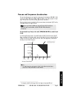
Non-conductive or conductive contents
In practice, the SITRANS LC500 probe is usually insulated. If the vessel contents are non-
conductive, the dielectric is composed of the vessel contents and the insulation, and the
separation distance is from the probe to the tank wall. The tank wall is the reference
electrode, and it must be connected to the ground point on the instrument.
If the vessel contents are conductive, the electrode must be insulated. In this case the
dielectric is the insulation layer and the interface between the conductive contents and
the insulating sleeve acts as the reference electrode. This reduces the separation
distance for the filled portion of the tank to the thickness of the insulation. It also creates
a linear reference electrode independent of the tank wall.
1.
This formula applies to a centrally mounted probe: for a probe mounted off-centre, the
formula must be adjusted.
Note:
For simplicity, the probe is shown centrally mounted. If it is to be mounted off-
centre, take care to ensure the electrode remains parallel to the tank wall.
C
K
L
Log D d
--------------------------
=
dielectric = contents plus insulation (non-conductive contents)
dielectric = insulation (conductive contents)
(insulation)
probe
sleeve
internal
tank wall
probe
dia. (d)
internal tank diameter (D)


