Siemens AG Österreich
1
of 8
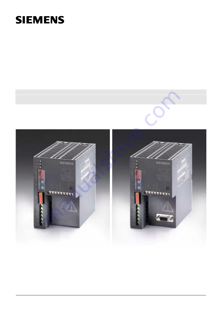
SITOP power DC-UPS Module 15
SITOP power DC-USV-Modul 15
6EP1931-2EC01
6EP1931-2EC11
Betriebsanleitung Order No.: C98130-A7508-A10-01-19
Operating Instructions
Page 1: ... 1 of 8 SITOP power DC UPS Module 15 SITOP power DC USV Modul 15 6EP1931 2EC01 SITOP power DC UPS Module 15 6EP1931 2EC11 Betriebsanleitung Order No C98130 A7508 A10 01 19 Operating Instructions 6EP1931 2EC01 6EP1931 2EC11 ...
Page 2: ...ren Fall der Aufstellung des Betriebes oder der Instandhaltung berücksichtigen Technische Änderungen jederzeit vorbehalten Note These operating instructions do not purport to cover all details of the product nor to provide for every possible contingency that may arise during installation operation or maintenance Subject to change without notice Einstellung R143 Zuerst Warnhinweise lesen Adjustment...
Page 3: ...uls erfolgt mit einstellbarem Konstantstrom bis zur eingestellten Ladeschlussspannung Ladeschlussspannung UA2 26 3 bis 29 2V DC Ladestrom IA2 0 3 bis 0 7A DC Einstellungen Einstellung der Zuschaltschwelle Sinkt die Eingangsspannung unter den eingestellten Wert der Zuschaltschwelle so schaltet das USV Modul in den Pufferbetrieb um Die Verbraucher werden dann ausschließlich durch das Akkumodul verso...
Page 4: ...nung auf 20 4V gesunken ist und eine Zwangsabschaltung zum Schutz des Akkus unmittelbar bevor steht Nach Abschaltung des Akkus aufgrund Überlast Kurzschluss Tiefentladeschutz oder abgelaufener Pufferzeit erlischt die rote Leuchtdiode Alarm der Relaiskontakt X2 5 X2 6 bleibt geschlossen Belastbarkeit der Relaiskontakte 60V DC 1A oder 30V AC 1A Signal Klartext Pufferbereitschaft vorhanden Pufferbere...
Page 5: ...t current IA1 15A DC Output characteristic of charging regulator The battery module is charged at an adjustable constant current until the set end of charge voltage is reached End of charge voltage vA2 26 3 to 29 2V DC Charging current IA2 0 3 to 0 7A DC Settings Setting the cut in threshold If the input voltage drops below the selected cut in threshold voltage the UPS module switches over to floa...
Page 6: ...isconnection to protect the battery is imminent When the battery has been disconnected due to overload short circuit exhaustive discharge protection or buffering timeout the red LED Alarm goes out but relay contact X2 5 X2 6 remains closed Contact rating 60V DC 1A or 30V AC 1A Signal Text Battery ready Battery not ready BUFRD ALARM Normal operation Not normal operation DC_OK DC_LO Not floating ope...
Page 7: ...5 55 65 75 85 95 105 115 125 135 145 155 165 175 185 195 205 215 225 235 245 255 265 275 285 295 305 315 max 1 1 1 1 1 1 1 1 1 1 1 1 1 1 1 1 1 1 1 1 1 1 1 1 1 1 1 1 1 1 1 1 0 0 0 0 0 0 0 0 0 0 0 0 0 0 0 0 0 1 1 1 1 1 1 1 1 1 1 1 1 1 1 1 1 x 0 0 0 0 0 0 0 0 1 1 1 1 1 1 1 1 0 0 0 0 0 0 0 0 1 1 1 1 1 1 1 1 x 0 0 0 0 1 1 1 1 0 0 0 0 1 1 1 1 0 0 0 0 1 1 1 1 0 0 0 0 1 1 1 1 x 0 0 1 1 0 0 1 1 0 0 1 1 0 0...
Page 8: ...m Published by Elektronikwerk Wien EWW Electronics Plant Vienna Bereich Group A D Siemensstrasse 88 92 Siemens AG Österreich All rights reserved A 1210 Wien Liefermöglichkeiten und technische Änderungen vorbehalten Delivery conditions and technical content subject to changes ...