100–% Stator Earth Fault Protection with 20 Hz Voltage Injection (ANSI 64G - 100%)
195
7UM62 Manual
C53000-G1176-C149-3
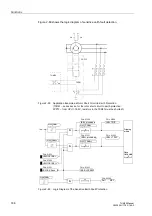
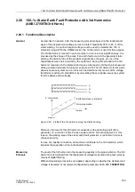
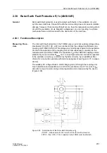
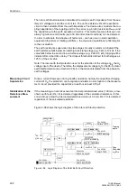
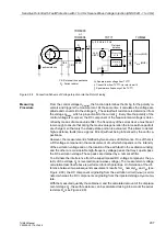
The driving 20 Hz voltage is picked up directly at the loading resistor via a voltage di-
vider. In addition, the 20 Hz current flow is measured via a miniature CT. Both quanti-
ties (U
SEF
and I
SEF
) are fed to the protection device.
The voltage to be injected into the generator starpoint depends on the driving 20 Hz
voltage (voltage divider: load resistor and band pass), and on the transformation ratio
of the neutral or earthing transformer.
To prevent the secondary load resistance from becoming too small (it should be > 0.5
Ω,
where possible), a high secondary rated voltage should be chosen for the earthing
or neutral transformer. 500 V has proven to be a good value.
Figure 2-93
Circuit Design of the 100-% Stator Earth Fault Protection with Earthing Trans-
former or Neutral Transformer (see also Figure A-43 in the Appendix).
The same measuring principle can also be used with a primary loading resistor. The
20 Hz voltage is connected in this case via a voltage transformer, and the starpoint
current is directly measured. The connection scheme, and hints on circuit design, can
be found in the Appendix A.5 (Figure A-43).
Measuring
Procedure
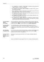
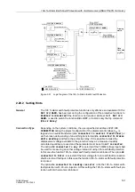
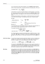
From the two measured quantities U
SEF
and I
SEF
in Figure 2-93, the 20 Hz current and
voltage vectors are calculated, and from the resulting complex impedance the ohmic
fault resistance is determined. This method eliminates disturbances caused by the
stator earth capacitance, and ensures a high sensitivity. The measuring accuracy is
further increased by using mean current and voltage values obtained over several cy-
cles for calculating the resistance.
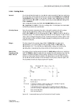
The model takes into account a transfer resistance R
PS
that may be present at the
neutral, earthing or voltage transformer. Other error factors are taken into account in
the angle error.
~
~
~
Supply voltage
(DC or AC)
G
20 Hz
GS
3
~
a
b
a
b
L
K
l
k
Neutral transformer
Band pass
Earthing
transformer
20 Hz generator
7UM62
Prot. Relais
Min. CT
(400 A / 5 A)
500 V
U
Nom
3
3
U
SEF
I
SEF
500 V
200 V
R
Loading resistor
U
SEF
Displacement voltage at protective relay
I
SEF
Measuring current at protective relay
R


