A.5 100–% Stator Earth Fault Protection with Primary Load Resistor
499
7UM62 Manual
C53000-G1176-C149-3
A.5
100–% Stator Earth Fault Protection with Primary Load Resistor
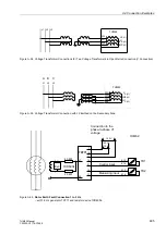
Some power systems with generators in unit connection have a load resistor installed
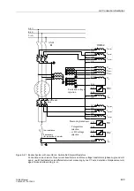
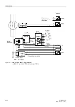
directly in the generator starpoint to reduce interference. Figure A-43 shows the con-
nection of the 20 Hz generator and the band pass in this application, and the integra-
tion of the protection device. The 20 Hz voltage is injected into the generator starpoint
via a powerful voltage transformer and drops off at the primary load resistor. In the
presence of an earth fault, an earth current flows through the CT in the starpoint. The
protection function detects and processes this current in addition to the 20 Hz voltage
(see also Section 2.29).
Figure A-43
Connection: 100–% Stator Earth Fault Protection to a Primary Load Resistor
Voltage
Transformer
Specification
An unearthed voltage transformer with a low primary-secondary impedance must
be used for the 20 Hz frequency.
Primary voltage:
U
N,Generator
/
√
3 (non-saturated up to U
N,Generator
)
Secondary voltage:
500 V
Power for 20 s
3 kVA
(50 Hz or 60 Hz)
Primary-secondary impedance
Zps < RL
at 20 Hz
(but at least < 1000
Ω
)
Can be obtained e.g. from:
Ritz Messwandlerbau
Salomon-Heine Weg 72
D-20251 Hamburg
(Phone +49 (0) 40511123 333)
Current
Transformer
Specification
As the transformation ratio is 1:1, a current transformer with a maximum number of
ampere windings must be chosen. The CT is installed directly in the starpoint on the
earth side, downstream of the load resistor.
Type:
5P10 or 5P15 (or 1FS10)
Rated secondary current:
1 A
Transformation ratio:
1 (1A/1A)
U
N
√
3
500 V
1A1
1B1
1A4
1A3
7XT34
1B4
4A1
4A3
7XT33
1A1
3A1
3A3
3A2
2A3
1A2
1A3
2A1
BI
20 Hz
band pass
20 Hz
generator
Supply
voltage
+U
H
-U
H
DC
AC
U
L1
U
L3
U
L2
External
blocking
Device
OK
R13
J8
R14
J7
U
E
I
EE1
7UM62
R
L
Transformation ratio 1:1
Voltage
transformer

