Configuration Notes
63
7SS52 V4 Manual
C53000-G1176-C182-3
4.4
Configuration Notes
The 7SS52 V4 can be applied for the protection of busbar configurations with quintu-
ple busbars as a maximum and up to 48 feeders.
•
When configuring the up to 12 busbar sections and 12 bus coupler sections you will
determine the description, busbar section number and colour for the individual bus-
bar sections (BB01 to BB12) or bus coupler sections (TB01 to TB12).
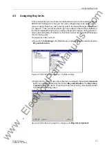
The evaluation report allows you to check the parameter assignments of the plant
configuration (see Figure 4-37, page 89).
•
2-bay bus couplers must be parameterized to bay units with successive numbers
(Figure 7-1, page 260).
•
In 2-bay-couplers you can configure one or two current transformers
(Chapter 7.1.3.2, page 259 and Chapter 7.1.3.3, page 259).
•
For each bay unit you may configure not more than one transfer bus isolator.
Transfer bus operation is only possible with transfer bus isolators of different bay
units.
•
Only switchgear or current transformers of the same bay may be assigned to a bay
unit. Except sectionalising isolators.
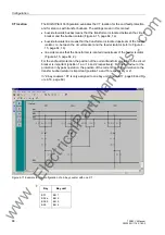
An example of a triple busbar with transfer busbars is shown in Figure 4-15, page 64.
The corresponding configuration data are collected in Table 4-1, page 65.
An example of a double busbar with a combination busbar is shown in Figure 4-16,
page 66. The corresponding configuration data are collected in Table 4-2, page 66.
Note
A feeder bay must include at least one isolator, one current transformer and one circuit
breaker (if end fault protection is used).
A coupler must include at least two isolators and one current transformer.
Note
Gaps in the configuration (e.g. reserve bays) are allowed.
www
. ElectricalPartManuals
. com


