Installation and Commissioning
8-11
7SA522 Manual
C53000-G1176-C119-2
8.1.3
Hardware Modifications
8.1.3.1
General
Hardware modifications might be necessary or desired. For example, a change of the
pick-up threshold for some of the binary inputs might be advantageous in certain ap-
plications. Terminating resistors might be required for the communication bus. In ei-
ther case, hardware modifications are needed. The modifications are done with jump-
ers on the printed circuit boards inside the 7SA522. Follow the procedure below,
“Jumpers on the Printed Circuit Boards”, whenever hardware modifications are done.
Power Supply
Voltage
There are different ranges for the power supply voltage of the various power supplies.
Refer to the data for the 7SA522 ordering numbers in Section A.1 of the Appendix. The
power supplies with the ratings 60/110/125 VDC and 110/125/220/250 VDC are inter-
convertible. Jumper settings determine the rating. The assignment of these jumpers
to the supply voltages are illustrated below, under “Jumpers on the Printed Circuit
Boards”. When the relay is delivered, these jumpers are set according to the name-
plate sticker. Generally, they need not be altered.
Nominal Currents
Jumper settings determine the rating of the current input transducers of the device.
When the relay is delivered, these jumpers are set according to the name-plate sticker
to 1 A or 5 A. The physical arrangements of these jumpers that correspond to the dif-
ferent current ratings are described below, “Jumpers on the Printed Circuit Boards”.
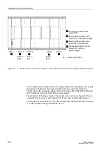
All these jumpers (X61 to X64 and X60) must be in the same position: 1 A or 5 A.
If the highly sensitive current input is fitted, jumper X64 is omitted (refer to table 8-6).
Control Voltages
for Binary Inputs
When the device is delivered from the factory, the binary inputs are set to operate with
a DC control voltage that corresponds to the rated DC voltage of the power supply. In
general, to optimize the operation of the inputs, the pick-up voltage of the inputs
should be set to most closely match the actual control voltage being used. Each binary
input has a pick-up voltage that can be independently adjusted; therefore, each input
can be set according to the function performed.
A jumper position is changed to adjust the pick-up voltage of a binary input. The phys-
ical arrangement of the binary input jumpers in relation to the pick-up voltages is ex-
plained below, “Jumpers on the Printed Circuit Boards”.
Note:
If nominal current ratings are changed, then the new ratings must be recorded under
address
in the
(see Sub-section 6.1.1).
Note:
If the 7SA522 performs trip circuit monitoring, two binary inputs, or one binary input
and a resistor, are connected in series. The pick-up voltage of these inputs must be
less than half of the nominal DC voltage of the trip circuit.
Summary of Contents for siprotec 7SA522
Page 20: ...7SA522 Manual C53000 G1176 C119 2 ...
Page 64: ...7SA522 Manual C53000 G1176 C119 2 ...
Page 89: ...SIPROTEC 4 Devices 4 25 7SA522 Manual C53000 G1176 C119 2 Figure 4 20 CFC Logic example ...
Page 408: ...7SA522 Manual C53000 G1176 C119 2 ...
Page 456: ...7SA522 Manual C53000 G1176 C119 2 ...
Page 516: ...7SA522 Manual C53000 G1176 C119 2 ...
Page 620: ...Appendix B 48 ...


