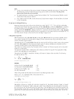


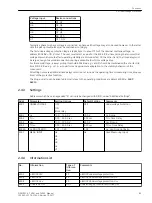


Voltage input
Device connections
Ue
Q9, Q10
Uf
Q11, Q12
Typically a phase-to-phase voltage is connected, a phase-earth voltage may also be used however. In the latter
case the pickup thresholds must be matched accordingly
The setting of limit values and time delays of the overvoltage protection depends on the speed with which the
voltage regulator can regulate voltage variations. The protection must not intervene in the regulation process
of the faultlessly functioning voltage regulator. For this reason, the two-stage characteristic must always be
above the voltage time characteristic of the regulation procedure.
The long-time stage 4102
U>
and 4103
T U>
must intervene in case of steady-state overvoltages. It is set to
approximately 110 % to 115 % U4103
T U>
and, depending on the regulator speed, to a range between 1.5 s
and 5 s.
In case of a full-load rejection of the generator, the voltage increases first in relation to the transient voltage.
Only then does the voltage regulator reduce it again to its nominal value. The U>> stage is set generally as a
short-time stage in a way that the transient procedure for a full-load rejection does not lead to a tripping.
Usual are e.g. for 4104
U>>
about 130 % U
N
with a delay 4105
T U>>
from zero to 0.5 s.
All setting times are additional time delays which do not include the operating times (measuring time, dropout
time) of the protective function.
The dropout ratio can be adapted at the address 4106
U> DOUT RATIO
in small stages to the operating
conditions and used for highly precise signalizations (e.g. network infeed of wind power stations).
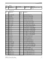
Settings
Addresses which have an appended “A” can only be changed with DIGSI, under “Additional Settings”.
Addr.
Parameter
Setting Options
Default Setting
Comments
4101
OVERVOLTAGE
OFF
ON
Block relay
OFF
Overvoltage Protection
4102
U>
30.0 .. 200.0 V
115.0 V
U> Pickup
4103
T U>
0.00 .. 60.00 sec
3.00 sec
T U> Time Delay
4104
U>>
30.0 .. 200.0 V
130.0 V
U>> Pickup
4105
T U>>
0.00 .. 60.00 sec
0.50 sec
T U>> Time Delay
4106A
U> DOUT RATIO
0.90 .. 0.99
0.95
U>, U>> Drop Out Ratio
4107
MEAS. INPUT
Ua
Ub
Uc
Ud
Ue
Uf
Ua
Used Measuring Input
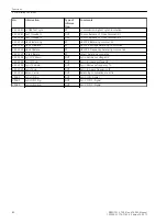
Information List
No.
Information
Type of
Informa-
tion
Comments
6513
>BLOCK O/V
SP
>BLOCK overvoltage protection
6516
>BLOCK U>
SP
>BLOCK overvoltage protection U>
6517
>BLOCK U>>
SP
>BLOCK overvoltage protection U>>
6565
Overvolt. OFF
OUT
Overvoltage protection switched OFF
2.5.3
2.5.4
Functions
2.5 Overvoltage Protection
86
SIPROTEC 4, 7VE61 and 7VE63, Manual
C53000-G1176-C163-3, Edition 10.2017
Summary of Contents for SIPROTEC 4 7VE61
Page 8: ...8 SIPROTEC 4 7VE61 and 7VE63 Manual C53000 G1176 C163 3 Edition 10 2017 ...
Page 24: ...24 SIPROTEC 4 7VE61 and 7VE63 Manual C53000 G1176 C163 3 Edition 10 2017 ...
Page 142: ...142 SIPROTEC 4 7VE61 and 7VE63 Manual C53000 G1176 C163 3 Edition 10 2017 ...
Page 192: ...192 SIPROTEC 4 7VE61 and 7VE63 Manual C53000 G1176 C163 3 Edition 10 2017 ...
Page 222: ...222 SIPROTEC 4 7VE61 and 7VE63 Manual C53000 G1176 C163 3 Edition 10 2017 ...
Page 230: ...230 SIPROTEC 4 7VE61 and 7VE63 Manual C53000 G1176 C163 3 Edition 10 2017 ...
Page 256: ...256 SIPROTEC 4 7VE61 and 7VE63 Manual C53000 G1176 C163 3 Edition 10 2017 ...
Page 314: ...314 SIPROTEC 4 7VE61 and 7VE63 Manual C53000 G1176 C163 3 Edition 10 2017 ...
Page 316: ...316 SIPROTEC 4 7VE61 and 7VE63 Manual C53000 G1176 C163 3 Edition 10 2017 ...
Page 330: ...330 SIPROTEC 4 7VE61 and 7VE63 Manual C53000 G1176 C163 3 Edition 10 2017 ...