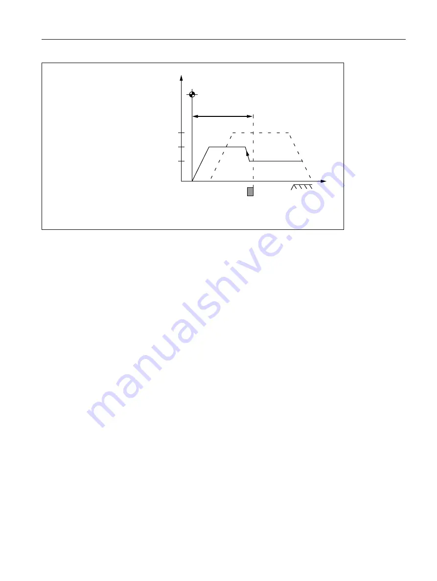
R1: Reference point approach
15.5 Referencing with incremental measurement systems
Basic Functions
Function Manual, 09/2011, 6FC5397-0BP40-2BA0
1217
Figure 15-10 Reference point position
When the reference point is reached the machine axis is stopped and the actual value system of the machine
axis is synchronized with the reference point value specified by the PLC user program.
MD34100 $MA_ REFP_SET_POS [ n] (Reference point value)
The reference point value is specified by the PLC user program via:
DB31, ... DBX2.4 / .5 / .6 / .7 (reference point value 1 / 2 / 3 / 4)
The reference point value, which was selected by the PLC user program at the time of the arrival of the reference
cam in Phase 1 (DB31, ... DBX12.7 = 1), is taken over by the NC.
The machine axis is now referenced. As identification, the NC sets the appropriate interface signal depending on
the active measuring system:
DB31, ... DBX60.4 / .5 (Referenced/Synchronized 1 / 2) = 1
Features of phase 3
• Feed override active.
• Feed stop (channelspecific and axisspecific) is active.
• NC STOP and NC START are active.
Special feature of phase 3
If the parameterized distance from the encoder zero mark to the reference point, i.e. the sum of reference point
distance and reference point offset (M MD34090) is smaller than the required breaking distance for
stopping from the reference point positioning velocity(MD34070), the machine axis initially stops "behind" the
reference point and then travels back to it.
(Reference point approach velocity)
Reference
point cam
DELAY
of reference
point approach
Velocity
(Reference point creep velocity)
(Reference point positioning velocity)
Zero mark
Distance
MD34100 $MA_REFP_SET_POS [0/1/2 or 3]
MD34080 $MA_REFP_MO
MD34090 $MA_REFP_MOVE_DIST_CORR
MD34040 $MA_REFP_VELO_SEARCH_MARKER
MD34070 $MA_REFP_VELO_POS
MD34020 $MA_ REFP_VELO_SEARCH_CAM


