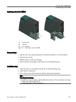
Removal steps
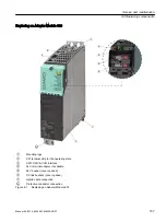
1. Open the fan cover using a suitable tool
①
(slotted screwdriver or Torx screwdriver).
2. Open the fan cover
②
.
3. Remove the fuses
③
by hand. You must always remove both fuses together.
Installation steps
To install the AM600, perform the removal steps in the reverse order.
Note
Checking the fastenings
● Attach the fan cover using a suitable slotted screwdriver or Torx screwdriver and check that
the connections are secure.
Tightening torque: 1.8 Nm (15.9 lbf in)
9.2.5
Replacing a fan in the Adapter Module 600
Preparatory steps
1. Disconnect the drive line-up.
2. Allow unimpeded access to the Adapter Module 600 (AM600).
3. Check that the cabinet is de-energized.
WARNING
Electric shock when replacing the fan
Because of the DC link capacitors, a hazardous voltage is present for up to five minutes after
the power supply has been switched off.
Contact with live parts can result in death or serious injury.
● Switch the power supply off before replacing the fan.
● Wait at least 5 minutes after switching off.
● Before starting any work, also check that the system is in a voltage-free state by measuring
at the DC link terminals DCP and DCN.
● Only use the following fan module with fans:
– Siemens article number: Fan module AM600 6SL3566-0AA00-0AA0
Service and maintenance
9.2 Replacing components
162
Manual, 06/2019, 6SL3097-5AW00-0BP1
Summary of Contents for Sinamics S120M
Page 2: ......
Page 20: ...Introduction 1 8 General Data Protection Regulation 18 Manual 06 2019 6SL3097 5AW00 0BP1 ...
Page 56: ...System overview 3 5 System Data 54 Manual 06 2019 6SL3097 5AW00 0BP1 ...
Page 110: ...S120M 5 11 Motor holding brake 108 Manual 06 2019 6SL3097 5AW00 0BP1 ...
Page 118: ...DRIVE CLiQ Extension 6 6 Technical data 116 Manual 06 2019 6SL3097 5AW00 0BP1 ...
Page 126: ...Hybrid Cabinet Bushing 7 6 Technical data 124 Manual 06 2019 6SL3097 5AW00 0BP1 ...
Page 182: ...Appendix A 2 Documentation overview 180 Manual 06 2019 6SL3097 5AW00 0BP1 ...
Page 185: ......


