background image

Overview 


Basic Operator Panel 2 (BOP-2) 

16


Operating Instructions, 02/2016, A5E37143404B AA 


Note 
Reaction to change between HAND and AUTO mode 
When changing from HAND to AUTO mode the Inverter reacts in the following manner: 


If the ON signal is active, the new setpoint will become active, and the Inverter 

automatically ramps the motor to the new setpoint. 

When changing from AUTO to HAND mode the Inverter reacts in the following way: 


The Inverter does not top the motor running. The Inverter runs the motor at the same 

speed that was set prior to the   key being pressed. Any ramp function that was in 

progress is stopped. 


Locking and unlocking the keypad 

To lock the BOP-2 keypad press   and   simultaneously for 3 seconds or more. To 

unlock the keypad press   and   simultaneously for 3 seconds or more. 

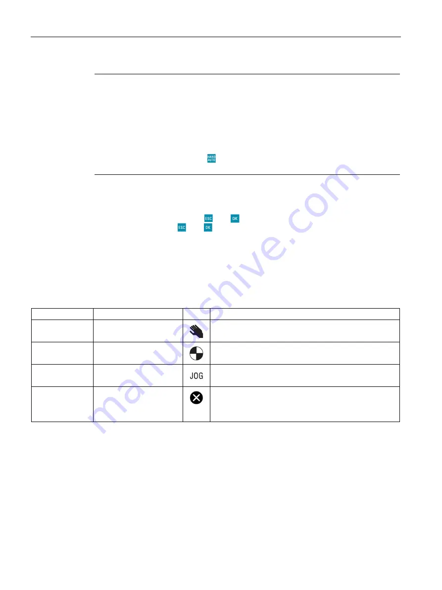
Screen icons 

The BOP-2 displays a number of icons at the left side of the display to indicate the actual 

state of the Inverter. These icons are explained in the following table. 

Table 4- 3 

Screen icons description 

Function 

Status 

Icon 

Remarks 

Command source  Hand 


When the HAND mode is active the icon is displayed. When 

AUTO mode is active, no icon is displayed. 

Inverter status 

Inverter and motor running 


The icon is static and does not rotate. 

Jog 

Jog function is active 


Fault/alarm 

Fault or alarm pending 
Flashing symbol = Fault 
Steady symbol = Alarm  


If a fault is detected, the Inverter will be stopped and the user 

is required to take the necessary corrective actions to clear 

the fault. An alarm is a condition that will not stop the Inverter, 

for example, overtemperature. 

Summary of Contents for SINAMICS BOP-2

Page 1: ......

Page 2: ......

Page 3: ...__ ___________________ ___________________ ___________________ ___________________ SINAMICS BOP 2 SINAMICS G Basic Operator Panel 2 BOP 2 Operating Instructions Edition 02 2016 02 2016 A5E37143404B AA Changes in this manual 1 Fundamental safety instructions 2 Safety notes 3 Overview 4 Installation 5 Monitoring 6 Control 7 Diagnostics 8 Parameters 9 Setup 10 Extras 11 Technical data 12 ...

Page 4: ...ted only by personnel qualified for the specific task in accordance with the relevant documentation in particular its warning notices and safety instructions Qualified personnel are those who based on their training and experience are capable of identifying risks and avoiding potential hazards when working with these products systems Proper use of Siemens products Note the following WARNING Siemen...

Page 5: ...nts 1 Changes in this manual 7 2 Fundamental safety instructions 9 2 1 General safety instructions 9 2 2 Industrial security 10 3 Safety notes 11 4 Overview 13 5 Installation 19 6 Monitoring 21 7 Control 23 8 Diagnostics 27 9 Parameters 33 10 Setup 37 11 Extras 43 12 Technical data 49 Index 51 ...

Page 6: ...Table of contents Basic Operator Panel 2 BOP 2 6 Operating Instructions 02 2016 A5E37143404B AA ...

Page 7: ...ng process can be found at the following link New commissioning process https support industry siemens com cs ww en view 109480663 Safety Notes The Warning notification and been upgraded to a Danger notification Safety notes Page 11 Overview List of compatible products has been updated Overview Page 13 Menu structure has been updated with the new commissioning process Overview Page 13 Setup Menu S...

Page 8: ...Changes in this manual Basic Operator Panel 2 BOP 2 8 Operating Instructions 02 2016 A5E37143404B AA ...

Page 9: ...ere injuries or death can occur Observe the safety instructions given in the hardware documentation Consider the residual risks for the risk evaluation WARNING Danger to life or malfunctions of the machine as a result of incorrect or changed parameterization As a result of incorrect or changed parameterization machines can malfunction which in turn can lead to injuries or death Protect the paramet...

Page 10: ...or more information visit this address http support automation siemens com WARNING Danger as a result of unsafe operating states resulting from software manipulation Software manipulation e g by viruses Trojan horses malware worms can cause unsafe operating states to develop in your installation which can result in death severe injuries and or material damage Keep the software up to date You will ...

Page 11: ...t is essential to ensure that the system is in a safe and stable state as some commissioning processes have the potential to start the motor Therefore it is important to secure any loads and ensure that should the motor start no potentially dangerous conditions exist NOTICE Fitting and removal of the Operator Panel The BOP 2 can be fitted to and removed from the inverter while power is applied ...

Page 12: ...Safety notes Basic Operator Panel 2 BOP 2 12 Operating Instructions 02 2016 A5E37143404B AA ...

Page 13: ...nverters The BOP 2 connects to the Inverter through an RS232 interface The BOP 2 automatically recognize all variants of the following Control Units from the SINAMICS range SINAMICS G120 CU230P 2 SINAMICS G120 CU240B 2 SINAMICS G120 CU240E 2 SINAMICS G120 CU250S 2 SINAMICS G120C Note BOP 2 functional support The BOP 2 supports all of the previously listed Control Units with firmware version 4 3 Se...

Page 14: ... and functions The controls display and connections of the BOP 2 are shown in the following figure Image 4 1 Layout of the BOP 2 Table 4 1 Description of BOP 2 physical characteristics Item Description Release catch LCD screen Door mounting screw recess Interface to Inverter Product rating label ...

Page 15: ...owing functions If pressed for less than 2 seconds the BOP 2 returns to the previous screen When a displayed value has been edited the new value is not saved If pressed longer than 3 seconds the BOP 2 returns to the status screen When using the ESC key in the parameter edit mode no data is saved unless the OK key has been pressed The ON key has the following functions In AUTO mode the ON key is no...

Page 16: ...ss and simultaneously for 3 seconds or more To unlock the keypad press and simultaneously for 3 seconds or more Screen icons The BOP 2 displays a number of icons at the left side of the display to indicate the actual state of the Inverter These icons are explained in the following table Table 4 3 Screen icons description Function Status Icon Remarks Command source Hand When the HAND mode is active...

Page 17: ...w Basic Operator Panel 2 BOP 2 Operating Instructions 02 2016 A5E37143404B AA 17 Menu structure The BOP 2 is a menu driven device and has the following basic menu structure Image 4 2 BOP 2 Basic menu structure ...

Page 18: ...E37143404B AA Note Menu structure and functionality The actual menu structure and functionality of the BOP 2 is influenced by the following factors The software version and type of Control Unit to which the BOP 2 has been fitted The firmware and software version of the BOP 2 ...

Page 19: ...to its non volatile memory which does not require power to retain the data To fit the BOP 2 to the Control Unit the following procedure should be performed 1 Place the bottom edge of the BOP 2 casing into the lower recess of the Control Unit housing 2 Push the BOP 2 towards the Control Unit until the release catch clicks into place on the Control unit housing Image 5 1 Fitting the BOP 2 to the Con...

Page 20: ...ator Panel The BOP 2 will then establish communications between the Operator Panel and the Control Unit Once communications have been established an internal check is performed to ensure that the Operator Panel is re sponding correctly Once all checks have been completed the BOP 2 will display the standard status screen The BOP 2 is now ready for use After establishing communications if a fault or...

Page 21: ...nu Use the and keys to scroll through the various screens The information displayed in the Monitoring screens is read only and cannot be modified Monitoring screen information The details of the information displayed by the various monitoring screens are described below The default screen shows the value set for the setpoint below this value the actual speed of the motor is displayed The voltage o...

Page 22: ...ing The RPM and current screen displays the actual rotational speed of the motor in RPM and the actual output current from the Inverter to the motor The voltage and current screen displays the actual voltage being supplied by the Inverter to the motor and the actual current output from the Inverter to the motor The voltage and RPM screen display the actual voltage being supplied by the Inverter to...

Page 23: ...he required menu Pressing will confirm the selection and display the top level menu The Inverter must be in HAND mode before any functions can be accessed If HAND mode is not selected a notice screen is displayed stating that the Inverter is not in HAND mode The HAND mode is selected by pressing the key Note Hand Auto mode If the key is pressed when the Inverter is in AUTO mode the user is taken d...

Page 24: ...he Inverter is set back to AUTO mode the setpoint previously used in AUTO mode becomes the valid setpoint Note Torque setpoint In HAND mode the torque setpoint if the Inverter is in torque control mode cannot be directly modified using the setpoint speed function of the BOP 2 although the motor can still be stopped and started using the and keys respectively To change or modify the value of the se...

Page 25: ... displayed The process of editing the individual digits is shown in the following figure Image 7 2 Editing individual digits Jog The Jog function when selected will allow the motor to be manually rotated by a pre determined value with each press of If is pressed continuously the motor will rotate continuously until is released To enable or disable the Jog function the actions shown in the followin...

Page 26: ...the REVERSE function Reverse The Reverse function when selected will allow the motor to be manually rotated in the reverse direction from its normal forward motion with each press of If is pressed continuously the motor will rotate continuously in reverse until is released To enable or disable the Reverse function the actions shown in the following figure should be performed Image 7 4 Reverse func...

Page 27: ...at all faults are acknowledged before restarting the system To acknowledge all active faults the actions shown in the following figure should be performed Image 8 1 Acknowledge faults sequence Active faults and alarms When the Inverter detects a fault or alarm condition the Inverter maintains a list of all the currently active faults and alarms For a detailed explanation of the displayed fault and...

Page 28: ...ry option within the Diagnostics menu maintains a list of the last 64 faults that have occurred within the Inverter motor system For a detailed explanation of the displayed fault and alarm numbers please refer to the relevant Parameter List Pressing for more than 3 seconds returns the BOP 2 display to the status screen To access the faults and alarm list the actions shown in the following figure s...

Page 29: ... the status words can help diagnose problems with the Inverter The status option displays the current state of the following control and status words Control word 1 Control word 2 Status word 1 Status word 2 The various screens displayed in this menu option are read only and cannot be modified Pressing for more than 3 seconds returns the BOP 2 display to the status screen To access the Status scre...

Page 30: ...Control Word 2 The indi vidual bits indicate the state of the fixed frequency setpoint Drive Da tasets and the technology controller In the Parameter Lists Control Word 2 is known as supplementary control word r0055 0 15 Control Word 2 higher bits The screen displays the higher eight bits of Control Word 2 The indi vidual bits indicate the state of the DC brake droop control torque control externa...

Page 31: ...ini mum speed current threshold speed threshold ramp function generator and DC link threshold r0053 0 11 Status Word 2 higher bits The screen displays the higher eight bits of Status Word 2 The indi vidual bits indicate the state of the DC link threshold limit exceeded ramp up ramp down completion technology controller output lower limit and technology controller output higher limit r0053 0 11 Sta...

Page 32: ...Diagnostics Basic Operator Panel 2 BOP 2 32 Operating Instructions 02 2016 A5E37143404B AA ...

Page 33: ...xpert filter this filter gives access to all the Inverter parameters The parameters can be addressed by the following methods Parameter number Parameter number and index number Parameter number and bit number Parameter number index number and bit number NOTICE Action on fault during parameter editing If a fault occurs during parameter editing the fault screen must be exited by pressing or in order...

Page 34: ...ers these are Single digit Scrolling Single digit editing of the parameters is accomplished by a long press of the key Each individual digit of the parameter can be modified using the and keys and individual confirmed by a press of the key This method of editing the parameters are shown in the following figure the symbol denotes where the display will automatically display a new screen on the comp...

Page 35: ...d by scrolling through to the parameters until the required parameter is displayed Press the key to confirm the parameter selection the displayed parameter value starts to flash Using the and keys increase or decrease the parameter value Press the key to confirm the value The actions required to perform the editing of parameters by scrolling is shown in the following figure ...

Page 36: ...Parameters Basic Operator Panel 2 BOP 2 36 Operating Instructions 02 2016 A5E37143404B AA Image 9 3 Editing parameters scrolling method ...

Page 37: ...isplayed Editing parameters Parameters can be modified use two methods scrolling through the parameter values or using the single digit methods See Parameters Page 33 NOTICE Important information on the latest changes to the firmware There has been some major changes to the way that the commissioning software has been implemented and it is recommended that you read all the information given at the...

Page 38: ...rted CAUTION Macro selection During the commissioning process the user is prompted to select a Macro that automatically configures the input signals output signals command source and setpoint source for the system Each Control Unit has their own unique functionality and therefore each Control Unit has a different set of macros available for selection Detailed wiring diagrams relating to the macros...

Page 39: ...Setup Basic Operator Panel 2 BOP 2 Operating Instructions 02 2016 A5E37143404B AA 39 Image 10 2 Standard commissioning Part 1 ...

Page 40: ...Setup Basic Operator Panel 2 BOP 2 40 Operating Instructions 02 2016 A5E37143404B AA Image 10 3 Standard commissioning Part 2 ...

Page 41: ...Setup Basic Operator Panel 2 BOP 2 Operating Instructions 02 2016 A5E37143404B AA 41 Image 10 4 Standard commissioning Part 3 ...

Page 42: ...Setup Basic Operator Panel 2 BOP 2 42 Operating Instructions 02 2016 A5E37143404B AA ...

Page 43: ...rters ROM FROM CRD reads parameter data from the memory card into the Inverter memory TO CARD writes parameter data from the Inverter memory on to the memory card FROM BOP reads parameter data from the BOP 2 to the Inverter memory TO BOP writes parameter data from the Inverter memory to the BOP 2 The actions to perform the previously mentioned functions are shown in the following figures Drive res...

Page 44: ...denotes where the screen automatically displays a new screen on the completion of a process Image 11 2 Extras save data from RAM to ROM To BOP This function writes the parameter data stored in the Inverter to be copied to the memory of the BOP 2 The memory in the BOP 2 is non volatile so data is retained until it is overwritten by another copy command The symbol denotes where the screen automatica...

Page 45: ...anges are automatically saved to the default parameter set 0 on the memory card if a memory card is already inserted into the memory card reader Therefore parameter set 0 is not displayed as an option when saving parameter sets to a memory card with the BOP 2 During the saving process the user is given the option to selected a unique number between 1 and 99 under which the parameter set will be st...

Page 46: ...Extras Basic Operator Panel 2 BOP 2 46 Operating Instructions 02 2016 A5E37143404B AA Image 11 5 Extras writing data to the memory card ...

Page 47: ...en the option to selected a unique number between 0 and 99 which then loads the parameter set stored under that number on the memory card to the Inverter s memory Should the user select a parameter set that does not actually exist on the memory card the BOP 2 displays a cloning error The symbol denotes where the screen automatically displays a new screen on the completion of a process Image 11 6 E...

Page 48: ...Extras Basic Operator Panel 2 BOP 2 48 Operating Instructions 02 2016 A5E37143404B AA ...

Page 49: ...rotection Depending upon the Control Unit IP rating to a max of IP55 Dimensions H x W x D 106 86 mm x 70 mm x 19 6 mm Net weight 0 10 Kg 0 22 lbs Gross weight 0 17 Kg 0 37 lbs Operating ambient temperature 0 50 C 32 122 F under nominal conditions of the attached inverter Transport and storage ambient temperature 40 70 C 40 158 F Humidity Maximum absolute humidity 25 g m3 ...

Page 50: ...Technical data Basic Operator Panel 2 BOP 2 50 Operating Instructions 02 2016 A5E37143404B AA ...

Page 51: ...lter 33 Extras 43 RAM to ROM 44 reading data from BOP 45 reading data from memory card 47 Saving data to BOP 44 saving data to memory card 45 F From BOP 45 Functional support 13 Functions 14 G Gross weight 49 H HAND AUTO 16 History 28 Humidity 49 I Icons 16 Initial startup 20 Installation 19 fitting the BOP 2 19 removing the BOP 2 19 J Jog 25 reverse function 26 K Keys 15 L Layout 14 Locking keypa...

Page 52: ... Power supply 19 Protection level 49 R Reverse 26 S Saving data from BOP 45 from memory card 47 RAM to ROM 44 To BOP 44 to memory card 45 Screen icons 16 Setpoint 24 Setup 37 Specifications 49 dimensions 49 gross weight 49 humidity 49 net weight 49 Operating temperature 49 protection level 49 storage temperature 49 Transport temperature 49 standard commissioning Macro selection 38 Standard commiss...

Page 53: ......

Page 54: ......

Reviews: