6.4.2
Terminal box
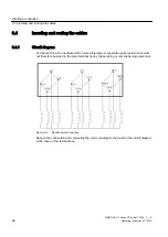
Figure 6-4
Terminal box 1XB1631
The connecting cables are inserted via cable glands with 4 x M80 x 2 threaded holes into the
terminal box. The cable glands are not included in the standard scope of supply.
For more information, see:
● Introducing the cables into the terminal box and routing them (Page 69)
● Connecting cables with cable lugs (Page 70)
6.4.3
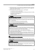
Introducing the cables into the terminal box and routing them
The connection cables are inserted into the terminal box via an exchangeable cable entry plate
or cable entry support . The cable entry plate is drilled by default. The cable glands are not
included in the standard scope of supply.
The cable entry can be turned by 180°.
Insert the cable into the terminal box
1. Unscrew the cable entry plate.
2. Drill the required number of holes or tapped holes in the required size into the cable entry
plate, if necessary. Ensure that the cable entry plate can be assembled after drilling and
that it features sufficient stiffness.
3. Fit the required cable glands.
4. Route the cables through the cable glands.
5. Fit the cable entry plate to the terminal box with the assembled cables.
6. Connect the ends of the cables to the terminals in accordance with the circuit diagram. The
circuit diagram is located in the cover of the terminal box.
Refer to the "Connecting cables..." section for more information.
Electrical connection
6.4 Inserting and routing the cables
SIMOTICS HT Series HT-direct 1FW4...1......A
Operating Instructions 11/2018
69
Summary of Contents for SIMOTICS HT Series
Page 2: ...13 11 2018 16 25 V5 00 ...
Page 10: ...Table of contents SIMOTICS HT Series HT direct 1FW4 1 A 10 Operating Instructions 11 2018 ...
Page 26: ...Description SIMOTICS HT Series HT direct 1FW4 1 A 26 Operating Instructions 11 2018 ...
Page 118: ...Service and Support SIMOTICS HT Series HT direct 1FW4 1 A 118 Operating Instructions 11 2018 ...
Page 122: ...Quality documents SIMOTICS HT Series HT direct 1FW4 1 A 122 Operating Instructions 11 2018 ...
Page 127: ......

