6.4.4
Connecting cables with cable lugs
1. Select the cable lugs according to the required cable cross-section and fixing screw or stud
size. Information about the maximum cross-section for the respective standard terminal
box design can be found in the catalog.
A sloped/angular arrangement of the supply cables is only permitted provided the required
minimum air clearances are met.
2. Remove the insulation from the conductor ends so that the remaining insulation reaches
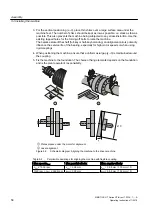
almost up to the cable lug
①
. Connect only one conductor per cable lug.
3. Fasten the cable lug to the end of the conductor correctly, e.g. by squeezing.
Figure 6-5
Connection with cable lug and fixing screw (schematic diagram)
4. Insulate the cable lug sleeves where necessary to ensure minimum air clearances and the
creepage distance are maintained.
5. Place the cable lug on the terminal support. If you are using a disconnecting link, check its
positioning.
6. Tighten the fixing element
②
with the corresponding tightening torque:
Fixing element
Tightening torque
Fastening screw M12
20 Nm
Fixing screws M16
40 Nm
Fixing nuts M12
20 Nm
See also
Tightening torques for screw and bolt connections (Page 119)
Electrical connection
6.4 Inserting and routing the cables
SIMOTICS HT Series HT-direct 1FW4...1......A
70
Operating Instructions 11/2018
Summary of Contents for SIMOTICS HT Series
Page 2: ...13 11 2018 16 25 V5 00 ...
Page 10: ...Table of contents SIMOTICS HT Series HT direct 1FW4 1 A 10 Operating Instructions 11 2018 ...
Page 26: ...Description SIMOTICS HT Series HT direct 1FW4 1 A 26 Operating Instructions 11 2018 ...
Page 118: ...Service and Support SIMOTICS HT Series HT direct 1FW4 1 A 118 Operating Instructions 11 2018 ...
Page 122: ...Quality documents SIMOTICS HT Series HT direct 1FW4 1 A 122 Operating Instructions 11 2018 ...
Page 127: ......


