


Functions
4.1 Cyclic and acyclic data exchange
PN/M-Bus LINK
16
Operating Instructions, 03/2018, A5E44260928-AA
Cyclic data exchange: Control and status information
The transmission of control and status information between the S7 controller and
PN/M-Bus LINK is performed via the cyclic IO process image.
In order to read measurement data from a specific M-Bus device, the S7 user program sets
the control bit for the respective M-Bus slave in the cyclic output data from the value "0" to
the value "1".
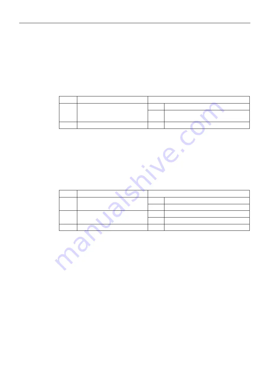
Table 4- 1
Cyclic output data (Byte 0)
Bit
Meaning
Value
0
Control bit for read request
0
No action
1
Read request to read measured data from
M-Bus device
1 ... 7
Not used
--
--
If the PN/M-Bus LINK accepts the call, it sets the corresponding status bit in the cyclic input
data from "0" to "1". After the PN/M-Bus LINK has read the measurement data from the
addressed M-Bus device, it sets the corresponding status bit in the cyclic input data
from "1" to "0".
If an error occurs during a read attempt, the PN/M-Bus LINK also sets the corresponding
status bit to "0" but sets the error bit at the same time. In this case, the data record does not
contain measured values.
Table 4- 2
Cyclic input data (Byte 0)
Bit
Meaning
Value
0
Status bit for read request
0
Device inactive
1
Read operation in progress
1
Error bit for feedback of the read
operation
0
No error occurred during last read operation
1
Error occurred during last read operation
2 ... 7
Not used
--
--


