


Application planning
3.6 Mounting cut-out
SIMATIC PC Panel PC 677/877, Control Unit
3-6
Operating Instructions, Edition 04/2005, A5E00407724-01
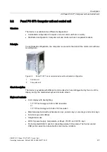
3.5.3
Type of fixation
The computer unit is secured in the installation cut-out either with clamps or screws.
Notice
Securing with screws is not possible with the 12" touch screen variant. For more information,
please refer to the chapter "Description."
Select the method of attachment suitable to your requirements for the degree of protection.
3.5.4
Degree of protection
Principle
The degree of protection provided by the front side can only be guaranteed when the
mounting seal lies completely against the mounting cut-out.
Caution
Please ensure that the material strength at the mounting cut-out is a maximum of 6 mm.
Please follow the specifications for the dimensions in the "Mounting cut-out" section.
The degrees of protection are only guaranteed when the following is observed:
•
The material strength at the mounting cut-out is at least 2 mm.
•
The deviation of the evenness of the mounting cut-out for installed control units relating to the
outside dimensions of the control unit is ≤ 0.5 mm.
Degree of protection IP65 and Nema 4
The degree of protection IP65 and Nema 4 are only guaranteed when clamps are secured
together with an encircling seal.
IP54 degree of protection
This degree of protection is provided for screw mounting.
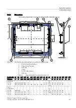
3.6
3.6
Mounting cut-out
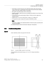
3.6.1
Select and complete recessed mounting cut-out
Requirements
The degree of protection suitable to the field of application and thereby the method of
attachment have been selected.
Procedure
1. Please follow the installation guidelines.
2. Select a location suitable for installation, taking into account the installation guidelines
and the chosen installation position.
3. On the basis of the dimension diagrams, check whether the required screw and pressure
points on the backside and the hatched seal area are easily accessible after the
completion of the installation cut-out. Otherwise the installation cut-out is useless.
4. Complete the installation cut-out according to the dimension diagrams.


