background image

Technische Daten 


IE/WSN-PA Link 

36


Kompaktbetriebsanleitung, 12/2012, A5E02509264-AD 

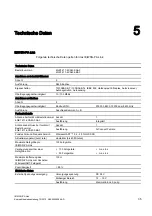
Technische Daten 

Erdung 

Erdungsklemme an der Unterseite des 

Geräts 

Stromaufnahme 

Maximal 

500 mA 

Elektromagnetische Verträglichkeit 

EMV-Zulassung: 

EN 61326-1:2006 

Zulässige Umgebungsbedingungen 

Während Betrieb, ohne Zubehör 

-40 °C ... +70 °C 

Umgebungstemperatur 

Während Betrieb, bei Nutzung des 

Harting Adapterkabels 

-25 °C ... +60 °C 

Relative Luftfeuchte 

Während Betrieb 

≤ 90 % 

Bauform, Maße und Gewicht 
Gehäuse 

Kupferarmes Aluminium 


Schutzart 

IP65 / NEMA 4X 

Abmessungen ohne Antenne (B x H 

x T) 

229 x 306 x 89 mm 


Gewicht 

4,54 kg 

Leitungseinführungen 
Dichtung 

4 Kabeldurchführungen 1/2" NPT 
Silikon 

Montagemöglichkeiten 

Wandmontage 

Produktfunktionen * 


Selbst organisierendes 

WirelessHART-Netzwerk 

Advanced Encryption Standard 

Verschlüsselung der WirelessHART-

Kommunikation nach der Spezifikation 

AES-128 

* Weitere Eigenschaften des Geräts finden Sie im folgenden Kapitel: 
Produktmerkmale (Seite 7)  

Summary of Contents for SIMATIC NET IE/WSN-PA Link

Page 1: ...__ ___________________ SIMATIC NET Industrial Ethernet Wireless HART IE WSN PA Link Kompaktbetriebsanleitung This document contains information in German page 1 and English page 47 12 2012 A5E02509264 AD Einleitung 1 Produktbeschreibung 2 Montage und Anschluss 3 Erstinbetriebnahme 4 Technische Daten 5 Zulassungen A Frequenzbereiche B ...

Page 2: ...n für die jeweilige Aufgabenstellung qualifiziertem Personal gehandhabt werden unter Beachtung der für die jeweilige Aufgabenstellung zugehörigen Dokumentation insbesondere der darin enthaltenen Sicherheits und Warnhinweise Qualifiziertes Personal ist auf Grund seiner Ausbildung und Erfahrung befähigt im Umgang mit diesen Produkten Systemen Risiken zu erkennen und mögliche Gefährdungen zu vermeide...

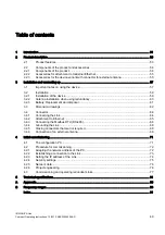
Page 3: ... Austausch und Entsorgung 15 3 3 Maßbilder 16 3 4 Anschluss 18 3 4 1 Anschließen des Link 18 3 4 2 Anschluss an Ethernet 19 3 4 3 Anschluss Modbus RTU RS485 20 3 4 4 Erdung des Link 22 3 4 5 Verschluss nicht benötigter Anschlüsse 22 3 4 6 Anschluss einer externen Antenne 23 4 Erstinbetriebnahme 25 4 1 Der Projektierungs PC 25 4 2 Vorgehensweise zur Inbetriebnahme 26 4 2 1 Netzwerkadresse des PC an...

Page 4: ...Inhaltsverzeichnis IE WSN PA Link 4 Kompaktbetriebsanleitung 12 2012 A5E02509264 AD ...

Page 5: ...1 6CA40 0AA0 IE WSN PA Link mit Redundanzfunktion und Anschluss für externe Antenne 6GK1 411 6CA40 0BA0 Eine externe Antenne ist als Zubehör verfügbar siehe Kapitel Zubehör für Gerätevariante mit Anschluss für externe Antenne Seite 9 Verwendete Begriffe und Abkürzungen Link In diesem Dokument wird die Bezeichnung Link stellvertretend für die vollständige Produktbezeichnung IE WSN PA Link verwendet...

Page 6: ...ernzugriff auf Aufzeichnung der Systemaktivität SysLog Fehlerbereinigung Redaktionelle Überarbeitung Abgelöste Dokumentation Das vorliegende Handbuch ersetzt die Handbuchausgabe 10 2011 Aktuelle Handbuchausgabe und weitere Informationen im Internet Die aktuelle Ausgabe dieses Handbuchs und weitere Informationen zu dem Produkt finden Sie auch auf den Internet Seiten des Siemens Automation Customer ...

Page 7: ...nte mit integrierter Antenne Die wesentlichen Eigenschaften sind WirelessHART Kommunikation entsprechend HART V7 Anbindung von WirelessHART Geräten an Ethernet Beobachtung von WirelessHART Geräten Konfiguration über Web Dienste Externe Versorgungsspannung Das IE WSN PA Link besitzt Anschlussklemmen zur Einspeisung einer externen Versorgungsspannung DC 24 V 500 mA Ethernet Das IE WSN PA Link ist zu...

Page 8: ... ab Firmware Version 4 3 17 für die Gerätevariante mit Anschluss für eine externe Antenne zur Verfügung Für die Redundanz werden zwei Links über einen Switch an das gleiche Ethernet Subnetz angeschlossen Die beiden Links werden über ein Ethernet Kabel miteinander verbunden Management Kopplung Eines der beiden Links wird als aktives Gerät projektiert und führt im Normalfall die Kommunikation zwisch...

Page 9: ...ten finden Sie unter folgender Internet Adresse www harting com contact adresse Ethernetkabel SIMATIC NET IE FC Standard Cable GP 2x2 Bestell Nr 6XV1 840 2AH10 Das Kabel ist nicht für Erdverlegung geeignet Feldkonfektionierbarer M12 Stecker IE FC M12 Plug PRO Bestell Nr 6GK1 901 0DB20 6AA0 2 2 3 Zubehör für Gerätevariante mit Anschluss für externe Antenne Optionales Zubehör Hinweis Mindestdämpfung...

Page 10: ... 6GK5 792 6MN00 0AA6 Blitzschutzelement LP798 1N Bestell Nr 6GK5 798 2LP00 2AA6 Antennenkabel 10 m N Connect Male Male Flexible Connection Cable Bestell Nr 6XV1 875 5AN10 Antennenkabel 1 m N Connect Male Male Flexible Connection Cable Bestell Nr 6XV1 875 5AH10 2 4 GHz Kupplungsstück IWLAN RCoax N Connect Male Male Coupler Bestell Nr 6GK5 798 0CP00 1AA0 ...

Page 11: ...n des Gerätes zu beachten Generelle Hinweise WARNUNG Öffnen des Gerätes Öffnen Sie das Gerät nicht bei eingeschalteter Versorgungsspannung Generelle Hinweise für den Einsatz im Ex Bereich WARNUNG Explosionsgefahr beim Anschließen oder Abklemmen des Geräts In einer leicht entzündlichen oder brennbaren Umgebung dürfen keine Leitungen an das Gerät angeschlossen oder vom Gerät getrennt werden WARNUNG ...

Page 12: ...em Gehäuse die EGB Richtlinien EGB Elektrostatisch gefährdete Bauelemente Externe Spannungsversorgung Das IE WSN PA Link besitzt Anschlussklemmen zum Anschluss der externen Versorgungsspannung DC 24 V WARNUNG Nehmen Sie nur unbeschädigte Teile in Betrieb Hinweise zum Blitzschutz WARNUNG Lebensgefahr durch Blitzschlag Antennen im Außenbereich müssen sich im Fangbereich eines Blitzableiters befinden...

Page 13: ...trieb wenn Sie dazu Fragen haben 3 2 Montage 3 2 1 Installation des Geräts Mastbefestigung Der optimale Installationsort des IE WSN PA Link mit integrierter Antenne ist an einem Mast ca 1 50 m über der Oberkante einer Gebäudeaußenwand Bauseits wird ein geeignetes 2 Zoll Montagerohr benötigt Zwei 78 mm Mastschellen sind im Lieferumfang enthalten Montieren Sie das IE WSN PA Link wie folgt 1 Führen S...

Page 14: ...die Wandmontage des Link den Abbildungen in diesem Kapitel Befestigen Sie das Link mit 4 Schrauben an der Wand Die Schrauben sind nicht im Lieferumfang enthalten Art und Länge der Schrauben hängen von der Beschaffenheit der Wand ab Position der externen Antenne Gerätevariante 6GK1 411 6CA40 0BA0 Befestigen Sie die externe Antenne senkrecht und mit einem Abstand von ca 1 50 m zu Gebäuden oder größe...

Page 15: ...nthält eine Lithium Batterie Die Batterie muss bei Betrieb des Geräts entsprechend den zulässigen Umgebungsbedingungen siehe technische Daten nicht ausgetauscht werden Wenn die Batterie doch getauscht werden soll dann lassen Sie die Batterie nur vom Repair Center auswechseln Bei Fragen wenden Sie sich bitte an Ihre Service Stelle oder Ihren Vertriebspartner Entsorgung Batterien und Akkus sind recy...

Page 16: ...der IE WSN PA Link 16 Kompaktbetriebsanleitung 12 2012 A5E02509264 AD 3 3 Maßbilder Bohrbild 8QWHUH EGHFNXQJ I U XJDQJ X GHQ HOHNWULVFKHQ QVFKO VVHQ HQWIHUQHQ ROO 137 HZLQGHDQVFKOXVV 6W FN UGXQJVNOHPPH PP Bild 3 2 Bohrbild Maße in mm ...

Page 17: ...itung 12 2012 A5E02509264 AD 17 Antenne und Blitzschutzelement QWHQQH 17 01 01 QWHQQHQNDEHO P 9 1 OLW VFKXW HOHPHQW 3 1 3 QWHQQHQNDEHO P 9 OLW VFKXW HOHPHQW 3 1 3 QWHQQH 17 01 01 QWHQQHQNDEHO P 9 1 XSSOXQJ 3 Bild 3 3 Montage von Antenne und Blitzschutzelement an das Link ...

Page 18: ...Anschluss POE dies kann zu Schäden am PC Laptop führen Gehen Sie beim Anschluss des IE WSN PA Link wie folgt vor 1 Erden Sie das IE WSN PA Link siehe Kapitel Erdung des Link Seite 22 2 Schließen Sie das Ethernet LAN an die primäre Ethernet Anschlussbuchse P1 des Link über ein gekreuztes Ethernet Kabel an siehe Kapitel Anschluss an Ethernet Seite 19 Schließen Sie ggf ein zweites gekreuztes Ethernet...

Page 19: ...egung der Ethernet Leitung in Schutzrohren Die Durchführungen an der Unterseite des Gehäuses besitzen 1 2 NPT Gewinde welche zum Anschrauben von Wellrohr geeignet sind Verbinden Sie das Gehäuse mittels eines geeigneten Wellrohrs mit dem Rohrleitungssystem für die Kabelaufnahme und ziehen Sie die Ethernet Leitungen in das Rohrsystem ein Verwendung eines Ethernet Kabels für Außeninstallation Für die...

Page 20: ...l Anschließen des Link Seite 18 Modbus RTU Bei der Installation einer seriellen Modbus Verbindung muss die Verkabelung vom IE WSN PA Link zu der Modbus SPS oder dem dezentralen Modbus Leitsystem erfolgen Die Modbus Anschlüsse befinden sich oberhalb der Mitte des Klemmenblocks neben dem Anschluss für die Spannungsversorgung Bei der Modbus Schnittstelle ist die korrekte Polung der Anschlüsse erforde...

Page 21: ...ikationen beschreiben eine symmetrische Übertragungsleitung in einem Mehrpunkt Netzwerk Bis zu 32 können Teilnehmer in einem Netzwerk angeschlossen sein 7HLOQHKPHU 7HLOQHKPHU 7HLOQHKPHU Q ELV X P JOLFK EVFKOXVVZLGHUVW QGH QXU EHL KRKHU EHUWUDJXQJVJHVFKZLQGLJNHLW XQG JUR HQ HLWXQJVO QJHQ HUIRUGHUOLFK Bild 3 6 Typisches Zeidraht Mehrpunkt Netzwerk Die Abbildung zeigt ein typisches Zweidraht Mehrpunk...

Page 22: ...och an jedem Standort die lokalen bzw die für die Anlage geltenden Vorschriften Das Baugruppengehäuse muss in jedem Fall entsprechend den lokalen und im jeweiligen Land geltenden elektrotechnischen Vorschriften geerdet werden Die wirksamste Erdungsmethode ist eine Direktverbindung mit der Erde bei minimalem Widerstand Der neben den Klemmen der Spannungsversorgung liegende Erdungsanschluss S vgl Ab...

Page 23: ...seite Bild 3 7 Anschluss für externe Antenne Maßzeichnungen des Gehäuses und der Antennenmontage finden Sie in Kapitel Maßbilder Seite 16 Hinweis Mindestdämpfung von 4dB erforderlich Bei Verwendung der Antenne ANT792 6MN Antennengewinn 6 dBi muss das Antennenkabel eine Dämpfung von mindestens 4dB besitzen Dies wird durch das Antennenkabel 6XV1 875 5AN10 Länge 10 m erreicht Bei Verwendung des Anten...

Page 24: ...Montage und Anschluss 3 4 Anschluss IE WSN PA Link 24 Kompaktbetriebsanleitung 12 2012 A5E02509264 AD ...

Page 25: ...ng und Inbetriebnahme des Link fest welchen Personen welche Benutzerrolle zugewiesen werden soll Hinweise hierzu finden Sie in der Betriebsanleitung des IE WSN PA Link PDF 4 1 Der Projektierungs PC Voraussetzung für den Projektierungs PC Um auf die integrierten HTML Seiten des IE WSN PA Link zugreifen zu können benötigen Sie einen PC Laptop mit Internet Browser Microsoft Internet Explorer Version ...

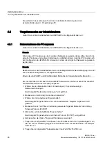
Page 26: ...Gigahertz Band Eine Liste von WHART und WLAN Kanälen finden Sie in Frequenzbereiche Seite 43 Um das IE WSN PA Link über die Standard IP Adresse zu erreichen müssen Sie zunächst die Netzwerkadresse des PC Laptop anpassen 1 Wählen Sie den Menübefehl Start Einstellungen Systemsteuerung Netzwerkverbindungen Das Dialogfeld Netzwerkverbindungen wird geöffnet 2 Markieren sie den Eintrag Local Area Connec...

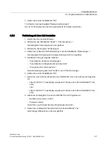
Page 27: ...tzwerk LAN wird geöffnet 5 Deaktivieren Sie ggf folgende Optionen Automatische Suche der Einstellungen Automatisches Konfigurationsskript verwenden Proxyserver für LAN verwenden Diese Einstellungen gelten nicht für DFÜ oder VPN Verbindungen 6 Klicken Sie auf die Schaltflächen OK 7 Geben Sie zum Start der Webseiten Ihres IE WSN PA Link in der Adresszeile folgendes ein https 192 168 1 10 werkseitig ...

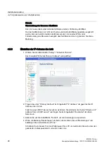
Page 28: ...Adresse des Link 1 Wählen Sie den Menübefehl Setup Ethernet Protocol Das Dialogfeld Ethernet Protocol Address wird geöffnet 2 Tragen Sie unter Primary Interface im Eingabefeld IP Address die gewünschte IP Adresse des Link ein Falls Sie einen DHCP Server benutzen aktivieren Sie alternativ die Option Obtain an IP address from a DHCP server und tragen Sie im Eingabefeld Hostname den Host Namen ein 3 ...

Page 29: ...den Eingabefeldern New Administrator Password und Confirm ein neues Passwort ein Zu den werkseitig eingestellten Passwörtern siehe Betriebsanleitung Kapitel Sicherheitseinstellungen und Benutzerrollen Hinweis Beim Ändern des Administrator Passwortes ist Vorsicht geboten Wenn das Administrator Passwort verloren geht können Sie das IE WSN PA Link nicht mehr in der Administratorrolle betreiben 3 Klic...

Page 30: ... im Eingabefeld Join key den Join Key Ihres WirelessHART Netzwerks als Hexadezimalzahl ein 4 Klicken Sie auf die Schaltfläche Submit 5 Wählen Sie den Menübefehl Setup Restart Apps Damit ist die Erstinbetriebnahme des IE WSN PA Link abgeschlossen Sie können den PC Laptop entfernen und die ursprünglichen Einstellungen des PC Laptop ggf wieder herstellen 4 2 6 Projektierung Projektierung Eine ausführ...

Page 31: ... gegenseitig Das Standby Gerät verfolgt auf der Funk Schnittstelle die Kommunikation des aktiven Geräts Bei Störungen und nach einer Umschaltung schickt das aktive Link einen Alarm an das verbundene Leitsystem Umschaltung zwischen aktivem Gerät und Standby Gerät Manuell können die beiden redundanten Geräte über die Web Schnittstelle umgeschaltet werden Sie tauschen dann ihre Rollen als aktives bzw...

Page 32: ...ennung der Management Kopplung Nach der Verbindung der zwei redundanten Geräte darf die Management Kopplung auf Port 2 der beiden Links nicht mehr getrennt werden Adressierung der redundanten Links durch das zentrale Leitsystem Die beiden redundanten Links werden vom Leitsystem als ein Gerät gesehen d h sie werden nur mit einer einzigen IP Adresse angesprochen Weitere Protokolle STP bzw RSTP könne...

Page 33: ...verbinden 4 Melden Sie sich mit der Rolle Administrator an 5 Navigieren Sie zur Web Seite Setup Redundancy und legen Sie Name und Positionierung für Link A und Link B fest 6 Navigieren Sie zur Seite Diagnostics Advanced Redundancy Status 7 Verbinden Sie die beiden Links Management Kopplung jeweils über Port 2 Ein Dialog erscheint auf der Web Seite Setup Redundancy 8 Klicken Sie auf die Schaltfläch...

Page 34: ...Erstinbetriebnahme 4 3 Inbetriebnahme und Betrieb redundanter Links IE WSN PA Link 34 Kompaktbetriebsanleitung 12 2012 A5E02509264 AD ...

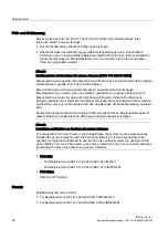
Page 35: ...00 bit s Ausführung Anschlussklemmen A B Funkschnittstelle Anzahl 1 Antenne bei Gerät mit Bestellnummer 6GK1 411 6CA40 0AA0 Ausführung Integriert Anzahl 1 Antennenanschluss bei Gerät mit Bestellnummer 6GK1 411 6CA40 0BA0 Ausführung N Connect Female Funktechnik und Frequenzbereich WirelessHART 2 4 2 5 GHz DSSS Aktualisierungszeit burst rate einstellbar bis 60 Minuten Maximale Netzgröße pro IE WSN P...

Page 36: ...ng Adapterkabels 25 C 60 C Relative Luftfeuchte Während Betrieb 90 Bauform Maße und Gewicht Gehäuse Kupferarmes Aluminium Schutzart IP65 NEMA 4X Abmessungen ohne Antenne B x H x T 229 x 306 x 89 mm Gewicht 4 54 kg Leitungseinführungen Dichtung 4 Kabeldurchführungen 1 2 NPT Silikon Montagemöglichkeiten Wandmontage Produktfunktionen Selbst organisierendes WirelessHART Netzwerk Advanced Encryption St...

Page 37: ...gt Siemens arbeitet mit Regierungsbehörden weltweit zusammen Ziel ist es vollständig normenkonforme Produkte anbieten zu können und das Risiko eines Verstoßes gegen nationale Vorschriften oder Gesetze über den Einsatz von WirelessHART Geräten auszuschalten Aktuelle Zulassungen im Internet SIMATIC NET Produkte werden regelmäßig für die Zulassungen hinsichtlich bestimmter Märkte und Anwendungen bei ...

Page 38: ...ochfrequenz Energie und kann Hochfrequenz Energie abstrahlen Das Gerät kann Empfangsstörungen bei Funk basierter Kommunikation verursachen wenn es nicht entsprechend den Anweisungen der Betriebsanleitung installiert wird Der Betrieb dieses Geräts im Wohnbereich führt voraussichtlich zu Empfangsstörungen In diesem Fall muss der Benutzer die Störungen auf eigene Kosten beseitigen Hinweis Installatio...

Page 39: ... outdoor locations NEMA Type 4X Temperature Code T4 Ta 40 C 60 C Canadian Standards Association CSA CSA Division 2 Non Incendive Suitable for Class I Division 2 Groups A B C and D Dust Ignition proof for Class II Groups E F and G Suitable for Class III Hazardous Locations Install per Siemens drawing A5E02467236A Temperature Code T4 Ta 40 C 60 C CSA Enclosure Type 4X Angaben zu Richtlinien der Euro...

Page 40: ...er für die EX Richtlinie relevanten Anwendung einsetzen wollen dann ist eine Abnahme durch Ihre zuständige Zulassungsstelle erforderlich N1 ATEX Typ n Siehe Hinweise unten Zertifikatnummer Baseefa10ATEX0044X ATEX Kennzeichnung II 3 G Ex nA nL IIC T4 Ta 40 C 60 C Nennspannung 28 V ND ATEX Dust Ignition proof Siehe Hinweis unten Zertifikatnummer Baseefa10ATEX0045X ATEX Kennzeichnung II 3 D Ex tD A22...

Page 41: ...iderstand der Antenne ist größer als ein Gigaohm Sie darf nicht mit einem trockenen Tuch oder Lösungsmittel abgerieben oder gereinigt werden um elektrostatische Aufladung zu vermeiden C Tick Das Gerät erfüllt die Anforderungen der Normen nach AS NZS 2064 Klasse A Zulassung für die Volksrepublik China Hinweis Die Installation des IE WSN PA Link muss von ausgebildetem Personal durchgeführt werden Na...

Page 42: ...Zulassungen IE WSN PA Link 42 Kompaktbetriebsanleitung 12 2012 A5E02509264 AD ...

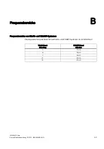
Page 43: ...2012 A5E02509264 AD 43 Frequenzbereiche B Frequenzbereiche von WLAN und WHART Systemen Überlappende Frequenzbereiche bei WLAN und WHART Systemen im 2 4 GHz Band WLAN Kanal 802 11b g WHART Kanal 802 15 4 1 11 16 6 15 20 7 16 21 11 20 25 13 21 25 ...

Page 44: ...Frequenzbereiche IE WSN PA Link 44 Kompaktbetriebsanleitung 12 2012 A5E02509264 AD ...

Page 45: ...ieren 6 Version 5 Frequenzbereiche 43 H Handbuch im Internet 6 Hardware Erzeugnisstand 5 L Lieferumfang IE WSN PA Link 8 M Management Kopplung 32 P Projektierungs PC anschließen 25 R Redundanz Bestellnummer 5 Inbetriebnahme 32 Voraussetzungen 31 W Warnmeldung Zertifikat 28 WHART Kanäle 43 WLAN Kanäle 43 WSN 5 Z Zertifikat public key 28 Zertifikat Warn Fehlermeldung 28 ...

Page 46: ...Index IE WSN PA Link 46 Kompaktbetriebsanleitung 12 2012 A5E02509264 AD ...

Page 47: ..._________ SIMATIC NET Industrial Ethernet Wireless HART IE WSN PA Link Compact Operating Instructions This document contains information in German page 1 and English page 47 12 2012 A5E02509264 AD Introduction 1 Product description 2 Installation and connecting up 3 Initial commissioning 4 Technical specifications 5 Approvals A Frequency ranges B ...

Page 48: ...operated only by personnel qualified for the specific task in accordance with the relevant documentation in particular its warning notices and safety instructions Qualified personnel are those who based on their training and experience are capable of identifying risks and avoiding potential hazards when working with these products systems Proper use of Siemens products Note the following WARNING S...

Page 49: ...edundancy 60 3 2 3 Battery Replacement and disposal 61 3 3 Dimension drawings 62 3 4 Connector 64 3 4 1 Connecting the Link 64 3 4 2 Attachment to Ethernet 65 3 4 3 Connecting the Modbus RTU RS 485 66 3 4 4 Grounding the Link 68 3 4 5 Closing connectors that are not required 68 3 4 6 Connection of an external antenna 68 4 Initial commissioning 71 4 1 The configuration PC 71 4 2 Procedure for commi...

Page 50: ...Table of contents IE WSN PA Link 50 Compact Operating Instructions 12 2012 A5E02509264 AD ...

Page 51: ...th integrated antenna 6GK1 411 6CA40 0AA0 IE WSN PA Link with redundancy function and connector for integrated antenna 6GK1 411 6CA40 0BA0 An external antenna is available as an accessory see section Accessories for the device variant with connector for external antenna Page 55 Terms and abbreviations acronyms used Link In this document the name Link is used in place of the full product name IE WS...

Page 52: ...Improved access protection with configurable passwords Remote access to recording of the system activity SysLog Errors corrected Editorial revision Replaced documentation This manual replaces the manual release 10 2011 Current manual release and further information on the Internet You will also find the current version of this manual and other information on the product on the Internet pages of Si...

Page 53: ...lessHART communication complying with HART V7 Connecting WirelessHART devices to Ethernet Monitoring WirelessHART devices Configuration using Web services External power supply The IE WSN PA Link has terminals for the connection of an external power supply 24 VDC 500 mA Ethernet The IE WSN PA Link is intended for operation in Ethernet networks Characteristics Connectors are designed for 10Base T a...

Page 54: ...et subnet The two Links are then interconnected via an Ethernet cable management connection One of the two Links is configured as the active device and this handles communication between the control center and WSN in a normal situation The second Link is used as the standby device 2 2 Components of the product and accessories 2 2 1 Components of the product What the consignment contains The follow...

Page 55: ...ble for underground installation M12 male connector IE FC M12 Plug PRO for assembly in the field Order no 6GK1 901 0DB20 6AA0 2 2 3 Accessories for the device variant with connector for external antenna Optional accessories Note Minimum attenuation of 4 dB required When using the ANT792 6MN antenna antenna gain 6 dBi the antenna cable must have an attenuation of at least 4 dB This is the case with...

Page 56: ...ssories IE WSN PA Link 56 Compact Operating Instructions 12 2012 A5E02509264 AD Antenna cable 1 m N Connect Male Male Flexible Connection Cable Order no 6XV1 875 5AH10 2 4 GHz coupling piece IWLAN RCoax N Connect Male Male Coupler Order no 6GK5 798 0CP00 1AA0 ...

Page 57: ...ing to it such as installation connecting up replacing devices or opening the device General notices WARNING Opening the device Do not open when energized General notices regarding use in hazardous areas WARNING Risk of explosion when connecting or disconnecting the device DO NOT CONNECT OR DISCONNECT EQUIPMENT WHEN A FLAMMABLE OR COMBUSTIBLE ATMOSPHERE IS PRESENT WARNING Risk of explosion when re...

Page 58: ...g is open ESD electrostatic sensitive devices External power supply The IE WSN PA Link has terminals for the connection of an external power supply 24 VDC WARNING Do not use any parts that show evidence of damage Notes on lightning protection WARNING Danger due to lightning strikes Antennas installed outdoors must be within the area covered by a lightning protection system Make sure that all condu...

Page 59: ...fied specialist company 3 2 Installation 3 2 1 Installation of the device Mast mounting The ideal installation location of the IE WSN PA Link with an integrated antenna is on a mast approximately 1 5 m above the top edge of an outside wall of the building A suitable 2 inch mounting pipe is required Two 78 mm mast clamps ship with the device Mount the IE WSN PA Link as follows 1 Place a mast clamp ...

Page 60: ... this section show the location of the holes for wall mounting of the Link Secure the Link to the wall with 4 screws The screws are not supplied with the device The type and length of the screws depend on the type of wall Position of the external antenna device variant 6GK1 411 6CA40 0BA0 Secure the external antenna in a vertical position and with a clearance of approximately 1 5 m from buildings ...

Page 61: ...contains a lithium battery The battery must not be replaced during operation of the device according to the permitted environmental conditions see technical specifications If the battery nevertheless does need to be replaced have the battery replaced only by the Repair Center If you have any questions please contact your service center or your marketing partner Disposal Batteries and rechargeable ...

Page 62: ...ngs IE WSN PA Link 62 Compact Operating Instructions 12 2012 A5E02509264 AD 3 3 Dimension drawings Drilling template RZHU FRYHU 5HPRYH IRU HOHFWULFDO FRQQHFWLRQV LQFK 137 FRQGXLW FRQQHFWLRQ SODFHV URXQG OXJ Figure 3 2 Drilling pattern dimensions in mm ...

Page 63: ...tructions 12 2012 A5E02509264 AD 63 Antenna and lightning protector QWHQQD 17 01 01 QWHQQHD FDEHO P 9 1 LJKWQLQJ SURWHFWRU 3 1 3 QWHQQHD FDEHO P 9 LJKWQLQJ SURWHFWRU 3 1 3 QWHQQD 17 01 01 QWHQQHD FDEHO P 9 1 RXSOHU 3 Figure 3 3 Installation of the antenna and lightning protector on the Link ...

Page 64: ...nk this can cause damage to the PC laptop To connect the IE WSN PA Link follow these steps 1 Ground the IE WSN PA Link see section Grounding the Link Page 68 2 Connect the Ethernet LAN to the primary Ethernet socket P1 of the Link using a crossover Ethernet cable see section Attachment to Ethernet Page 65 If necessary connect a second crossover Ethernet cable to connector P2 of the Link as describ...

Page 65: ...it system Using an Ethernet cable for outdoor installation The products recommended for outdoor installation can be found in the section Product description Page 53 Note that the Ethernet cable specified there is not suitable for underground installation Screw the adapter cable M12 female NPT 1 2 RJ 45 jack from the firm of Harting see section Product description Page 53 into the suitable outer ca...

Page 66: ...Modbus RTU is transmitted on a physical RS 485 layer Three DIP switches are used to create a network terminating resistor for the RS 485 circuit The switches are located inside the housing of the electronics on the RS 485 communications board in the center of the housing at the top Figure 3 5 DIP switches on the Modbus board With switch 2 ON a 120 ohm resistor is activated on the bus This is requi...

Page 67: ...th ends of the network The termination is however only intended for high transmission speeds above 115 kbps and over long cable lengths For the transmission speeds implemented with the IE WSN PA Link it is normally not necessary Serial connection Note With the normal systems this is as follows A Tx and B Rx Remember that this is sometimes reversed Connect 4 wire systems according to the following ...

Page 68: ...nector S located next to the power supply terminals see also the figure in the section Connecting the Link Page 64 is the internal ground connector screw see also section Connecting the Modbus RTU RS 485 Page 66 3 4 5 Closing connectors that are not required Close any connectors that are not required In the base of the connection box there are 1 2 holes for NPT cable feedthroughs that are closed i...

Page 69: ...hen using the ANT792 6MN antenna antenna gain 6 dBi the antenna cable must have an attenuation of at least 4 dB This is the case with the antenna cable 6XV1 875 5AN10 length 10 m When using the antenna cable 6XV1 875 5AN10 length 1 m an additional attenuator with at least 4 dB must be inserted in the cable External antennas of redundant Links You will find notes on installing the antennas of redun...

Page 70: ...Installation and connecting up 3 4 Connector IE WSN PA Link 70 Compact Operating Instructions 12 2012 A5E02509264 AD ...

Page 71: ...de who should be assigned which user role You will find more information in the operating instructions of the IE WSN PA Link PDF 4 1 The configuration PC Requirements for the configuration PC To be able to access the integrated HTML pages of the IE WSN PA Link you require a PC laptop with an Internet browser Microsoft Internet Explorer version 6 0 or higher recommended Mozilla Firefox 1 5 or highe...

Page 72: ... will find a list of WHART and WLAN channels in Frequency ranges Page 89 To be able to reach the IE WSN PA Link using the standard IP address you will first need to adapt the network address of the PC laptop 1 Select the menu command Start Settings Control Panel Network and Dial up Connections The Network connections dialog opens 2 Select the Local Area Connection entry 3 Select Properties in the ...

Page 73: ...N connections 6 Click the OK button 7 To start the Web pages of your IE WSN PA Link enter the following in the address line https 192 168 1 10 IP address set in the factory for the P1 LAN interface of the Link or https 192 168 2 10 IP address set in the factory for the P2 LAN interface of the Link 8 Enter the following in the Connect to IE WSN PA Link dialog User name login admin Password default ...

Page 74: ...ired IP address of the Link in the IP Address box under Primary Interface If you use a DHCP server on the other hand select the Obtain an IP address from a DHCP server option and enter the host name in the Hostname input box 3 Click the Submit button button to save the changes 4 If the Restart apps message appears click Restart apps and confirm this by clicking Yes In this case close the Web brows...

Page 75: ...odify the administrator password Enter a new password in the New Administrator Password and Confirm input boxes For information on the passwords set in the factory refer to the operating instructions section Security settings and user roles Note Use caution when changing the administrator password If the administrator password is lost you will not be able to operate the IE WSN PA Link from the adm...

Page 76: ...range 0 to 65535 are permitted 3 Enter the join key of your WirelessHART network in the Join key input box as a hexadecimal number 4 Click the Submit button 5 Select the Setup Restart Apps menu command This completes the initial commissioning of the IE WSN PA Link You can remove the PC laptop and restore the original settings on the PC laptop 4 2 6 Project engineering Project engineering You will ...

Page 77: ...monitor each other The standby device monitors the communication of the active device on the wireless interface If there is a disruption or following a failover the active link sends an alarm to the connected control system Failover between the active and standby device The two redundant devices can be switched over manually via the Web interface They then swap over their roles as active or standb...

Page 78: ...o disconnection of the management link After connecting the two redundant devices the management link at port 2 of the two Links must not be disconnected again Addressing of the redundant Links by the central control system The two redundant Links are considered to be one device by the control system in other words they are addressed with a single IP address Further protocols STP or RSTP can be us...

Page 79: ...o connect to the Link 4 Log on with the administrator role 5 Go to the Web page Setup Redundancy and specify the name and position for Link A and Link B 6 Go to the Diagnostics Advanced Redundancy Status page 7 Connect the two Links management connection in each case via port 2 A dialog appears on the Setup Redundancy Web page 8 Click the Form redundant pair button to connect the two Links to form...

Page 80: ...Initial commissioning 4 3 Commissioning and operating redundant Links IE WSN PA Link 80 Compact Operating Instructions 12 2012 A5E02509264 AD ...

Page 81: ...00 38400 19200 or 9600 bps Design Terminals A B Wireless interface Number 1 Antenna for device with order number 6GK1 411 6CA40 0AA0 Design Integrated Number 1 Antenna connector for device with order number 6GK1 411 6CA40 0BA0 Design N Connect Female Wireless technology and frequency range WirelessHART 2 4 2 5 GHz DSSS Update time burst rate Can be set up to 60 minutes Maximum network size per IE ...

Page 82: ...ing the Harting adapter cable 25 to 60 Relative humidity During operation 90 Design dimensions and weight Housing Low copper aluminum Degree of protection IP65 NEMA 4X Dimensions without antennas W x H x D 229 x 306 x 89 mm Weight 4 54 kg Cable guides Seal 4 cable feedthroughs 1 2 NPT Silicon Installation options Wall mounting Product functions Self organizing WirelessHART network Advanced Encrypt...

Page 83: ...nt bodies worldwide The aim is to supply fully compliant products and remove the risk of violating country directives or laws governing use of WirelessHart devices Current approvals on the Internet SIMATIC NET products are regularly submitted to the relevant authorities and approval centers for approvals relating to specific markets and applications You will also find the current approvals for the...

Page 84: ...y energy If not installed and used in accordance with the instruction manual this equipment may cause harmful interference to radio communications Operation of this equipment in a residential area is likely to cause harmful interference In which case users will be required to correct the interference at their own expense Note Installation and operation of devices with an external antenna To comply...

Page 85: ...de T4 Ta 40 C to 60 C Canadian Standards Association CSA CSA Division 2 Non Incendive Suitable for Class I Division 2 Groups A B C and D Dust Ignition proof for Class II Groups E F and G Suitable for Class III Hazardous Locations Install per Siemens drawing A5E02467236A Temperature code T4 Ta 40 C to 60 C CSA Enclosure Type 4X Information on directives of the European Union The product meets the r...

Page 86: ... an application to which hazardous areas directive applies you will need to obtain approval from the test center responsible N1 ATEX type n See notes below Certificate number Baseefa10ATEX0044X ATEX identification mark II 3 G Ex nA nL IIC T4 Ta 40 C to 60 C Rated voltage 28 V ND ATEX Dust Ignition proof See note below Certificate number Baseefa10ATEX0045X ATEX identification mark II 3 D Ex tD A22 ...

Page 87: ...ng N1 N7 ND and NF Note The sheet resistance of the antenna is greater than one gigaohm It must not be rubbed or cleaned with a dry cloth or solvent to avoid electrostatic charges C Tick The device meets the requirements of the AS NZS 2064 standards Class A Approval for the People s Republic of China Note The IE WSN PA Link may only be installed be trained personnel After purchase or installation ...

Page 88: ...Approvals IE WSN PA Link 88 Compact Operating Instructions 12 2012 A5E02509264 AD ...

Page 89: ...2 2012 A5E02509264 AD 89 Frequency ranges B Frequency ranges of WLAN and WHART systems Overlapping frequency ranges in WLAN and WHART systems in the 2 4 GHz band WLAN channel 802 11b g WHART channel 802 15 4 1 11 16 6 15 20 7 16 21 11 20 25 13 21 25 ...

Page 90: ...Frequency ranges IE WSN PA Link 90 Compact Operating Instructions 12 2012 A5E02509264 AD ...

Page 91: ...WSN PA Link product 54 Connecting the configuration PC 71 Current information 52 D Documentation 54 F FAQs 52 Field device 51 Firmware Update 52 Version 51 Frequency ranges 89 H Hardware product version 51 M Management link 78 Manual on the Internet 52 R Redundancy Commissioning 78 Order number 51 Requirements 77 W Warning message certificate 73 WHART channels 89 Wireless channels 89 WSN 51 ...

Page 92: ...Index IE WSN PA Link 92 Compact Operating Instructions 12 2012 A5E02509264 AD ...

Reviews: