background image

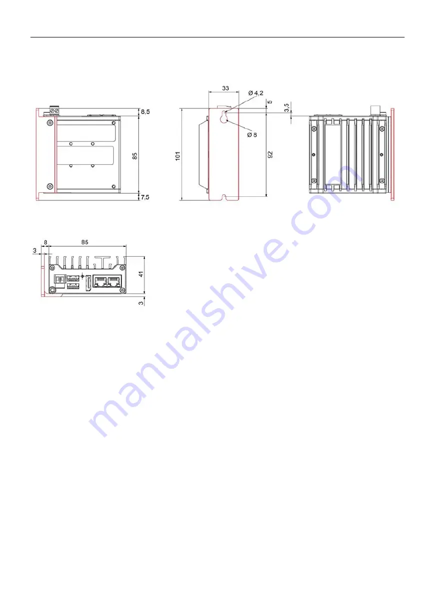
Dimension drawings 


9.1 Dimension drawing basic device 


SIMATIC IPC127E 

70


Operating Instructions, 01/2019, A5E44296915-AA 

Upright mounting  


All dimensions in mm 

Summary of Contents for SIMATIC IPC127E

Page 1: ... SIMATIC Industrial PC SIMATIC IPC127E Operating Instructions 01 2019 A5E44296915 AA Preface Overview 1 Safety instructions 2 Mounting and connecting the device 3 Commissioning the device and device functions 4 Device maintenance and repair 5 Technical specifications 6 Certificates and approvals 7 Directives and declarations 8 Dimension drawings 9 Hardware description 10 Technical support A Markin...

Page 2: ...ly by personnel qualified for the specific task in accordance with the relevant documentation in particular its warning notices and safety instructions Qualified personnel are those who based on their training and experience are capable of identifying risks and avoiding potential hazards when working with these products systems Proper use of Siemens products Note the following WARNING Siemens prod...

Page 3: ...ology is recommended Scope of validity of this document These operating instructions are valid for all versions of the SIMATIC IPC127E Scope of this documentation The documentation for the SIMATIC IPC127E consists of Product information e g Important notes on your device Quick Install Guide SIMATIC IPC127E SIMATIC IPC127E operating instructions in English and German If you ordered the device with ...

Page 4: ...Preface SIMATIC IPC127E 4 Operating Instructions 01 2019 A5E44296915 AA ...

Page 5: ...fication data of the device 21 3 1 3 Permitted mounting positions 23 3 2 Mounting the device 24 3 2 1 Mounting instructions 24 3 2 2 Mounting on a standard rail 26 3 2 3 Wall mounting 28 3 2 4 Upright mounting 29 3 2 5 Vertical mounting standard rail 30 3 3 Connecting the device 31 3 3 1 Notes on connecting 31 3 3 2 Connecting the protective conductor 33 3 3 3 Connecting the power supply 34 3 3 4 ...

Page 6: ... 5 8 Recycling and disposal 52 6 Technical specifications 53 6 1 General technical specifications 53 6 2 Ambient conditions 56 6 3 Power demand of the components 57 6 4 Direct current supply DC 58 7 Certificates and approvals 59 7 1 CE marking 59 7 2 DIN ISO 9001 certificate and software license agreements 59 7 3 UL61010 approval 59 7 4 FCC USA compliance 60 7 5 Canada 60 7 6 Australia 61 7 7 Eura...

Page 7: ...8 10 3 1 Currently allocated system resources 78 10 4 Input output address areas 78 10 4 1 Overview of the internal module registers 78 10 4 2 Watchdog register 79 10 4 3 MMIO GPIO addresses for LEDs and battery monitoring 82 A Technical support 83 A 1 Service and support 83 A 2 Troubleshooting 84 B Markings and symbols 87 B 1 Overview 87 B 2 Safety 87 B 3 Operator controls 87 B 4 Certificates app...

Page 8: ...Table of contents SIMATIC IPC127E 8 Operating Instructions 01 2019 A5E44296915 AA ...

Page 9: ... IPC127E Operating Instructions 01 2019 A5E44296915 AA 9 Overview 1 1 1 Product description 1 1 1 Overview SIMATIC IPC127E provides high level industrial functionality Compact design High degree of ruggedness ...

Page 10: ...ection 2 x RJ45 Ethernet connection X1 and X2 for 10 100 1000 Mbps Power button LEDs The on off button has three functions Switch on the PC Briefly press once Shut down operating system and switch off PC Briefly press once Switch off PC without shutting down the operating system hardware reset Press for more than 4 seconds Note The BIOS setup entry After Power Failure is preset to Power On This me...

Page 11: ...5 Ethernet connection X1 and X2 for 10 100 1000 Mbps Power button LED display The on off button has three functions Switch on the PC Briefly press once Shut down operating system and switch off PC Briefly press once Switch off PC without shutting down the operating system hardware reset Press for more than 4 seconds Note The BIOS setup entry After Power Failure is preset to Power On This means the...

Page 12: ... 1 2 Design of the devices SIMATIC IPC127E 12 Operating Instructions 01 2019 A5E44296915 AA Additional connections Extended device RJ45 Ethernet connection X3 for 10 100 1000 Mbps 2 x USB 3 0 port high current ...

Page 13: ... red 4 Hz Watchdog status display active L1 RUN STOP Off Green Can be controlled by user program control program Yellow L2 ERROR Off Red Can be controlled by user program control program Yellow L3 MAINT Off Yellow Can be controlled by user program control program Red Example programs for controlling the LEDs on Windows operating systems are available on the Customer Support page of Siemens Industr...

Page 14: ...4021 0AA20 0AA2 Vertical mounting Basic device 6AG4021 0AA20 0AA3 Vertical mounting Extended device 6AG4021 0AA20 0AA4 Vertical mounting standard rail 6AG4021 0AA20 0AA5 Lithium battery A5E44491494 Additional accessories can be found on the Internet at Service Support http www siemens com automation service support Expansion components and accessories http www automation siemens com mcms pc based ...

Page 15: ...ce in a control cabinet some areas or components in the open control cabinet may be carrying life threatening voltages If you touch these areas or components you may be killed by electric shock Switch off the power supply to the cabinet before opening it System expansions NOTICE Damage through system expansions Device and system expansions may be faulty and can affect the entire machine or plant T...

Page 16: ... not reverse polarity do not heat above 100 C and protect from direct sunlight moisture and condensation Strong high frequency radiation NOTICE Observe immunity to RF radiation The device has an increased immunity to RF radiation according to the specifications on electromagnetic compatibility in the technical specifications Radiation exposure in excess of the specified immunity limits can impair ...

Page 17: ...out industrial security please visit https www siemens com industrialsecurity Siemens products and solutions undergo continuous development to make them more secure Siemens strongly recommends that product updates are applied as soon as they are available and that the latest product versions are used Use of product versions that are no longer supported and failure to apply latest updates may incre...

Page 18: ...Safety instructions 2 3 Notes on use SIMATIC IPC127E 18 Operating Instructions 01 2019 A5E44296915 AA ...

Page 19: ...t damage immediately 3 Unpack the device at its installation location 4 Keep the original packaging in case you have to transport the unit again Note Damage to the device during transport and storage If a device is transported or stored without packaging shocks vibrations pressure and moisture may impact the unprotected unit A damaged packaging indicates that ambient conditions have already had a ...

Page 20: ...eratures or extreme fluctuations in temperature during transportation as is the case in cold weather for example moisture can build up on or inside the device condensation Moisture causes a short circuit in electrical circuits and damages the device In order to prevent damage to the device proceed as follows Store the device in a dry place Bring the device to room temperature before starting it up...

Page 21: ...late is located on the back panel of the device The COA label is only available in pre installed Windows operating systems and is affixed to the rear of the device Procedure 1 Transfer article number serial number production version FS and Ethernet addresses from the nameplate The Ethernet addresses can also be found in the BIOS Setup under Main Advanced Peripheral Configuration see section Techni...

Page 22: ...ns 01 2019 A5E44296915 AA Example of a COA label Microsoft Windows Product Key of the Certificate of Authenticity COA The COA label is only attached to the rear of the device when Windows is installed COA label of a device with operating system Windows 10 Enterprise LTSB 2016 64 bit MUI De En Fr It Sp ...

Page 23: ...tions The following mounting positions are permitted Observe the permitted temperature range for operation in the respective mounting position as defined in section Technical specifications Page 53 Ensure that the following clearances measurements to another component or to a wall of a housing are complied with Below the device 50 mm Above the device 50 mm ...

Page 24: ...tions Possible mounting types of the device Mounting on a standard rail Wall mounting Upright mounting Vertical mounting standard rail The mounting types are described in the following sections using the standard device as an example Position of the interfaces The position of the interface side is determined by the mounting of the mounting bracket For mounting on a standard rail the interface side...

Page 25: ...r times the total weight of the device including fixing elements NOTICE Incorrect fixing elements If you use anchors and screws other than those specified below for wall and vertical mounting safe mounting is not guaranteed The device can fall and may be damaged Use only the anchors and screws specified in the following table Material Bore diameter Fixing element Concrete Select according to the s...

Page 26: ...e inside of the device Tools A T10 screwdriver Procedure for mounting 1 Lay the standard rail bracket on the rear of the device Note the position of the spring of the standard rail bracket 2 Fasten the standard rail bracket with the four supplied screws 3 Place the device with the standard rail bracket onto the mounting rail from above If the device is tilted when you place it down the standard ra...

Page 27: ...tructions 01 2019 A5E44296915 AA 27 Procedure for dismantling 1 Press the device down until the lower rail guide frees the device 2 Swing the device out of the rails 3 Remove the device from the rail See also Dimension drawing basic device Page 67 Dimension drawing Extended device Page 71 ...

Page 28: ...e A T10 screwdriver Two anchors and two screws Procedure for mounting 1 Mark the fixing holes on the mounting sur face 2 Drill the fixing holes 3 Insert the anchors in the drilled holes 4 Place the mounting bracket on the rear of the device Note the orientation of the key hole bore holes of the mounting bracket 5 Fasten the mounting bracket with the four supplied screws 6 Place the device with the...

Page 29: ...ersions for the Standard and for the Extended device version Note Only use the supplied screws for fastening the mounting bracket Longer screws can damage the inside of the device A T10 screwdriver Two anchors and two screws Procedure Vertical mounting 1 Place the mounting brackets onto the mounting surface 2 Mark the fixing holes 3 Drill the fixing holes 4 Insert the anchors in the drilled holes ...

Page 30: ...t allows mounting that requires less space than wall mounting Requirement Mounting bracket Note Only use the supplied screws for fastening the mounting bracket Longer screws can damage the inside of the device A T10 screwdriver Two anchors and two screws Procedure Vertical mounting standard rail 1 Place the mounting bracket on the rear of the device 2 Fasten the mounting bracket with the two suppl...

Page 31: ...ke sure that the disconnector is easily accessible WARNING Risk of lightning strikes A lightning flash may enter the mains cables and data transmission cables and jump to a person Death serious injury and burns can be caused by lightning Take the following precautions Disconnect the device from the power supply in good time when a thunderstorm is approaching Do not touch mains cables and data tran...

Page 32: ...5E44296915 AA NOTICE Damage through regenerative feedback Regenerative feedback of voltage to ground by a connected or installed component can damage the device Connected or built in I Os for example a USB drive are not permitted to supply any voltage to the device Regenerative feedback is generally not permitted ...

Page 33: ...ge may be present in a defective device which can cause fire or an electric shock if touched Death and serious bodily injury can result Connect the device to the protective conductor before you put it into operation The PE terminal on the device must be connected to the protective conductor of the control cabinet or system in which the device is installed Never operate the device without protectiv...

Page 34: ...Note IEC EN UL 61010 Note the following when you operate the device according to IEC EN UL 61010 2 201 The device may only be connected to a 24 V DC power supply that meets the requirements of safe extra low voltage SELV PELV according to IEC EN UL 61010 2 201 In areas subject to UL CSA 61010 2 201 the device must be supplied with NEC Class 2 according to UL CSA 61010 2 201 or a limited energy cir...

Page 35: ... 3 3 Connecting the device SIMATIC IPC127E Operating Instructions 01 2019 A5E44296915 AA 35 Procedure 1 Switch off the 24 V DC power supply 2 Connect the wires of the power supply as shown 3 Insert the terminal at the indicated position ...

Page 36: ...MATIC NET Industrial Ethernet You can establish a network between the IPC and other devices via Industrial Ethernet The on board LAN interfaces are twisted pair interfaces with data transmission rates of 10 100 1000 Mbps Note You need a category 6 Ethernet cable for operation at 1000 Mbps PROFINET PROFINET can be operated via Standard Ethernet interfaces RT SIMATIC NET You can use this software pa...

Page 37: ...evices are identified with corresponding labels Any unprotected contact may cause burns Avoid direct contact with the device during operation Touch the device only with appropriate protective gloves Requirement The device is connected to the power supply The protective conductor is connected The connection cables are plugged in correctly The following hardware is available for initial commissionin...

Page 38: ...fault values in the BIOS Setup Procedure Switching on the device 1 The device starts as soon as 24 V are present Note The PC ON WD LED lights up The device carries out a self test During the self test the following message appears Press Esc for Boot Options 2 Wait for the message to disappear 3 Follow the instructions on the screen Procedure Switching off the device To turn off the device always s...

Page 39: ...reset of the computer Operating hours meter information on total runtime SIMATIC IPC DiagBase software Use the functions of the SIMATIC IPC DiagBase software included in the scope of delivery for local monitoring Use the DiagBase Management Explorer application to obtain a clear overview of the controls Use the DiagBase Alarm Manager to receive notifications about individual alarms Note For more i...

Page 40: ...re in proximity to the RAM ICs blocks Temperature of the basic module A temperature error is triggered when one of the three temperature values exceeds the set temperature threshold and the following reaction is initiated Reaction Option The DiagBase or DiagMonitor software is enabled None The temperature error is retained in memory until temperatures have fallen below the thresholds and it is res...

Page 41: ...ons The following reactions can occur if the watchdog is not addressed within the set time Option Reaction Reset on Executes a hardware reset when the watchdog expires Reset off Executes no action when the watchdog expires Restart Restarts the operating system when the watchdog expires Shutdown Shuts down the operating system when the watchdog expires NOTICE Reset on option The Reset on option imm...

Page 42: ...ackup battery has a limited service life see section Maintenance Page 43 A two tier battery monitoring checks the status of the backup battery The SIMATIC DiagBase and SIMATIC DiagMonitor diagnostic software determines the status of the backup battery When the first warning level is reached the battery for buffering CMOS data still has a remaining service life of at least one month ...

Page 43: ...placement interval SDD Depending on the type of use CMOS backup battery 5 years The interval for replacement of the flash drives SSD depends greatly on the type of use A specif ic interval cannot be given Note All drives are monitored by SIMATIC DiagBase or SIMATIC DiagMonitor software via SMART status As soon as the Smart status of the SSD goes to Not OK a message is generated in SIMATIC DiagBase...

Page 44: ...ions on RF suppression Contact your technical support team or where you purchased your PC to find out which system expansion devices may be installed If you install or exchange system expansions and damage your device the warranty and UL approval are voided CAUTION Electrostatic sensitive devices ESD The device contains electronic components which are destroyed by electrostatic charges This can re...

Page 45: ...ery every 5 years Replace the lithium battery only with the type recommended by the manufacturer The article number is A5E44491494 Do not throw lithium batteries into fire do not solder on the cell body do not recharge do not open do not short circuit do not reverse polarity do not heat above 100 C and protect from direct sunlight moisture and condensation CAUTION Danger of burns The surface of so...

Page 46: ...ch width across flats 1 5 mm Removing the backup battery NOTICE Time may be deleted The time will be deleted if it takes you longer than 30 seconds to replace the battery The device is no longer synchronous Time controlled programs will no longer run or will run at the wrong time This may damage the plant Reset the time for the device To remove the backup battery follow these steps 1 Remove the pr...

Page 47: ...e new battery by placing it on the Velcro tape Note Ensure that the cable connection is pointing in the direction of the printed circuit board 2 Fasten the cover of the housing side with the connections 3 Turn the heat sink around and slide it on the bottom of the housing Note Ensure that the EMC seal does not point up when sliding in the heat sink Make sure that the heat sink of the SSD when inst...

Page 48: ...cturer The article number is A5E44491494 Do not throw lithium batteries into fire do not solder on the cell body do not recharge do not open do not short circuit do not reverse polarity do not heat above 100 C and protect from direct sunlight moisture and condensation CAUTION Danger of burns The surface of some devices can reach temperatures of over 70 C These devices are identified with correspon...

Page 49: ...Removing the SSD To remove the SSD follow these steps 1 Remove the protective conductor connection 2 Remove the screws on the two connection sides and remove the covers 3 Remove the threaded pin on the heat sink 4 Remove the remaining screws on the heat sink 5 Slide the heat sink out in the direction of the arrow and rest the enclosure part on the cooling fins 6 Remove the marked screw and careful...

Page 50: ...he plug connector 3 As shown in the figure the heat sink must rest on the enclosure Check the position of the heat sink by carefully sliding the module back into the enclosure Correct the position of the heat sink if necessary 4 Position the spring in the heat sink so that the ring shaped part of the spring comes to rest above the screw sleeve then fasten the SSD again with the screw 5 Close the e...

Page 51: ...stalled software 5 5 2 1 Boot mode Note Setting Boot mode We recommend that you restore the target system in the Boot mode that was set in the delivery state Windows 10 UEFI Mode UEFI Unified Extensible Firmware Interface 5 5 2 2 Partitions under Windows 10 Partitioning the hard disk or the SSD drive For the Windows 10 operating system boots in UEFI mode GPT data storage medium the following parti...

Page 52: ... information about SIMATIC IPC Image Partition Creator refer to its product documentation 5 7 Configuring firmware BIOS You can find information on configuring firmware BIOS and on the firmware settings in the delivery state in the Firmware BIOS description https support industry siemens com cs ww en view 109762673 Note If your IPC no longer boots e g due to a crash during a BIOS update contact yo...

Page 53: ...45635 1 Degree of protection IP 40 in accordance with IEC 60529 Protection class Protection class I in accordance with IEC 61140 Degree of pollution Device is designed for environments with pollution degree 2 Quality assurance In accordance with ISO 9001 Note Note the following when you operate the device according to IEC EN UL 61010 2 201 The device may only be connected to a 24 V DC power supply...

Page 54: ... 80 2 GHz 80 AM according to IEC 61000 4 3 3 V m 2 6 GHz 80 AM according to IEC 61000 4 3 10 V 10 KHz 80 MHz 80 AM according to IEC 61000 4 6 Magnetic field 100 A m RMS value 50 60 Hz in accordance with IEC 61000 4 8 Main circuit board Processor main memory Intel Atom E3930 2 cores 2 threads 2 GB RAM Intel Atom E3940 4 cores 4 threads 4 GB RAM Intel Atom E3930 2 cores 2 threads 2 GB RAM TPM Intel ...

Page 55: ... the components Page 57 LAN interface X1 P1 RJ45 1 Intel LAN Controller Springville i210 10 100 1000 Mbps teaming 2 LAN interface X2 P1 RJ45 1 LAN interface X3 P1 RJ45 1 Ex tended device Monitor Can be connected via DisplayPort Keyboard mouse Connection via USB port 1 For unique labeling the LAN interfaces are numbered on the enclosure The numbering by the operating system can differ 2 Teaming can...

Page 56: ...g or mounting on a standard rail interfaces on side Vertical mounting standard rail interfaces top bottom CPU Intel Atom E3930 0 C to 45 C 50 C CPU Intel Atom E3940 0 C to 40 C 45 C Basic device Vertical mounting standard rail interfaces front CPU Intel Atom E3930 0 C to 35 C 40 C CPU Intel Atom E3940 0 C to 35 C 40 C Storage transport 20 60 C Gradient Operation Max 10 C h Storage 20 C h no conden...

Page 57: ...Storage transport 5 to 9 Hz 3 5 mm 9 to 500 Hz 9 8 m s2 Impact resistance Tested in accordance with IEC 60068 2 27 Operation 150 m s2 11 ms Storage transport 250 m s2 6 ms 6 3 Power demand of the components Maximum power consumption of the auxiliary components Auxiliary components Maximum permitted power consumption 5 V Max total power USB device 3 0 High current 900 mA 5 W for all USB devices Not...

Page 58: ...4 VDC 19 2 to 28 8 VDC Protection class Safety class I A protective conductor must be connected to the device Typical power consumption Power consumption at 24 V rated voltage Basic device with Intel Atom E3930 13 W Basic device with Intel Atom E3940 15 W Extended device with Intel Atom E3930 13 W Extended device with Intel Atom E3940 15 W See also Power demand of the components Page 57 ...

Page 59: ...lity management system for all production processes development production and sales meets the requirements of DIN ISO 9001 2000 This has been certified by DQS the German society for the certification of quality management systems Certificate registration no DE 000656 QM08 Software license agreements If the device is supplied with preinstalled software you must observe the corresponding license ag...

Page 60: ...ed to correct the inter ference at his own expense Shielded Cables Shielded cables must be used with this equipment to maintain compliance with FCC regulations Modifications Changes or modifications not expressly approved by the manufacturer could void the user s authority to operate the equipment Conditions of Operations This device complies with Part 15 of the FCC Rules Operation is subject to t...

Page 61: ...ion Customs Union EAC Identification for Eurasion Customs Union EAC Eurasian Conformity Customs union of Russia Belarus and Kazakhstan Declaration of conformity according to Technical Regulations of the Customs Union TR CU 7 8 Korea KOREA The following approvals are available for the device when specified as such on the nameplate The following approvals are available for the device when specified ...

Page 62: ...Certificates and approvals 7 8 Korea SIMATIC IPC127E 62 Operating Instructions 01 2019 A5E44296915 AA ...

Page 63: ...EU Electromagnetic Compatibility The device is designed for the following areas of application corresponding to the CE marking Scope of application Requirements for Interference emission Immunity to interference Industrial area EN 61000 6 4 EN 61000 6 2 Residential and commercial areas and small businesses EN 61000 6 3 EN 61000 6 1 2011 65 EU Restriction of the use of certain hazardous substances ...

Page 64: ... Device as a common international designation Electrostatic sensitive devices can be labeled with an appropriate symbol NOTICE Damage to ESD from touch Electrostatic sensitive devices ESD can be destroyed by voltages which are far below the human perception limit If you touch a component or electrical connections of a module without discharging any electrostatic energy these voltages may arise The...

Page 65: ...s the maximum electrostatic voltages with which a person is charged depending on humidity and material These values conform to the specifications of IEC 61000 4 2 Synthetic materials Wool Antistatic materials such as wood or concrete NOTICE Grounding measures There is no equipotential bonding without grounding An electrostatic charge is not discharged and may damage the ESD Protect yourself agains...

Page 66: ...station and devices tools and packaging used are properly grounded This way you avoid static discharge Avoid direct contact As a general rule do not touch electrostatic sensitive devices except in the case of unavoidable maintenance work Hold the modules at their edge so that you do not touch the connector pins or conductor paths This way the discharge energy does not reach and damage the sensitiv...

Page 67: ... 67 Dimension drawings 9 9 1 Dimension drawing basic device Note The fixing holes on the device are arranged symmetrically The fixing parts can be arranged to meet your requirements in any orientation of the device Mounting on a standard rail All dimensions in mm ...

Page 68: ...Dimension drawings 9 1 Dimension drawing basic device SIMATIC IPC127E 68 Operating Instructions 01 2019 A5E44296915 AA Vertical mounting standard rail All dimensions in mm ...

Page 69: ...Dimension drawings 9 1 Dimension drawing basic device SIMATIC IPC127E Operating Instructions 01 2019 A5E44296915 AA 69 Wall mounting All dimensions in mm ...

Page 70: ...Dimension drawings 9 1 Dimension drawing basic device SIMATIC IPC127E 70 Operating Instructions 01 2019 A5E44296915 AA Upright mounting All dimensions in mm ...

Page 71: ...g Instructions 01 2019 A5E44296915 AA 71 9 2 Dimension drawing Extended device Note The fixing holes on the device are arranged symmetrically The fixing parts can be arranged to meet your requirements in any orientation of the device Mounting on a standard rail All dimensions in mm ...

Page 72: ...Dimension drawings 9 2 Dimension drawing Extended device SIMATIC IPC127E 72 Operating Instructions 01 2019 A5E44296915 AA Vertical mounting standard rail All dimensions in mm ...

Page 73: ...Dimension drawings 9 2 Dimension drawing Extended device SIMATIC IPC127E Operating Instructions 01 2019 A5E44296915 AA 73 Wall mounting All dimensions in mm ...

Page 74: ...Dimension drawings 9 2 Dimension drawing Extended device SIMATIC IPC127E 74 Operating Instructions 01 2019 A5E44296915 AA Upright mounting All dimensions in mm ...

Page 75: ...from RAM 10 2 External interfaces 10 2 1 Overview of interfaces Interface Posi tion Description Basic Extended device USB Exter nal 2 4 USB channels 2 4 USB 3 0 Ethernet Exter nal 2 x RJ45 3 x RJ45 10 100 1000 Mbps DisplayPort Exter nal DP 10 2 2 USB 3 0 port Pin Short name Meaning Input output 1 VBUS 5 V fused Output 2 D Data channel USB2 Input output 3 D Data channel USB2 Input output 4 GND Grou...

Page 76: ...Lane1 DP data 1 Output 5 GND Ground 6 ML_Lane1 DP data 1 Output 7 ML_Lane2 DP data 2 Output 8 GND Ground 9 ML_Lane2 DP data 2 Output 10 ML_Lane3 DP data 3 Output 11 GND Ground 12 ML_Lane3 DP data 3 Output 13 CONFIG1 CAD Cable Adapter Detect Input 14 CONFIG2 Ground PullDown 15 AUX_CH Auxiliary channel Bidirectional 16 GND Ground 17 AUX_CH Auxiliary channel Bidirectional 18 HPD Hot Plug Detect Input...

Page 77: ...nal data A input output 3 BI_DB Bidirectional data B input output 4 BI_DC Bidirectional data C input output 5 BI_DC Bidirectional data C input output 6 BI_DB Bidirectional data B input output 7 BI_DD Bidirectional data D input output 8 BI_DD Bidirectional data D input output LED Short description Meaning 1 LED 1 Off 10 Mbps Lit green 100 Mbps Lit orange 1000 Mbps 2 LED 2 Lit orange Connection esta...

Page 78: ...w the current allocation of system resources or possible conflicts in the Control Panel Procedure To view the system resources proceed as follows 1 Select Start in the Windows Start menu 2 Enter msinfo32 in the search box and confirm with the ENTER key 10 4 Input output address areas 10 4 1 Overview of the internal module registers The following addresses are used for the internal registers Addres...

Page 79: ...ing any value to this register will reload the timer to prevent the timeout TCO Timer Status TCO_STS Offset 64h Bit Range Default Access Field Name ID Description 31 18 0h RO Reserved reserved2 Reserved 17 0h RW 1C V Second Timeout Status second_to_sts PMC sets this bit to 1 to indicate that the TIMEOUT bit had been or is currently set and a second timeout occurred before the TCO_RLD register was ...

Page 80: ...10 Don t load OS Hold in pre boot state and use LAN to determine next step 11 Reserved Reset on RSM_RST_N de assertion only 19 13 0h RO Reserved reserved2 Reserved 12 0h RW L TCO Lock tco_lock When set to 1 this bit prevents writes from changing the TCO_EN bit in offset 30h of Power Management I O space Once this bit is set to 1 it cannot be cleared by software writing a 0 to this location Reset i...

Page 81: ...mer each time the TCO RLD register is written Values of 0000h or 0001h will be ignored and should not be attempted The timer is clocked at approximately 0 6 seconds and thus allows timeouts ranging from 1 2 seconds to 613 8 seconds Note The timer has an error of 1 tick 0 6s The TCO Timer will only count down in the S0 and S0IX state 15 0 0h RO Reserved rsvd Reserved No Reboot PBASE Bus 0 Device 0x...

Page 82: ...ffset Bit 1 Battery Example Reg LED_USER1_RD_N_P1V8A 0xD0C506A0 Function Community Offset Direction Description LED 0x1A0 Out Low enable red User LED1 LED 0x1A8 Out Low enable green User LED1 LED 0x1C8 Out Low enable red User LED2 LED 0x1D0 Out Low enable green User LED2 LED 0x1E0 Out Low enable red User LED3 LED 0x198 Out Low enable green User LED3 LED 0x1C0 Out BIOS boot indicator Low OS Control...

Page 83: ...ens com sitrainworld AppLang en Industry Mall https mall industry siemens com When contacting your local representative or Technical Support please have the following information at hand MLFB of the device BIOS version for industrial PC or image version of the device Other installed hardware Other installed software Current documentation Always use the current documentation available for your prod...

Page 84: ...cted Check whether the power cord has been properly connected to the monitor and to the system unit or to the grounded shockproof outlet Check whether the monitor cable has been properly connected to the system unit and to the monitor If the monitor screen still remains dark after you have performed these checks and measures con tact your technical support team The mouse pointer does not appear on...

Page 85: ...ponding The USB ports are not correctly supported Turn on USB Legacy Support for mouse and keyboard For other devices you need the USB device drivers for the required operating system chkdsk is not functioning UWF Unified Write Filter is active The chkdsk command is not supported if the UWF is activated Deactivate the UWF or use an alternative method to chkdsk ...

Page 86: ...Technical support A 2 Troubleshooting SIMATIC IPC127E 86 Operating Instructions 01 2019 A5E44296915 AA ...

Page 87: ...ay vary in some details from the symbols shown in the following tables B 2 Safety Symbol Meaning Symbol Meaning Warning observe the supplied docu mentation Lock is closed Attention radio equipment Lock is open Disconnect the power plug before opening Opening for Kensington lock Attention ESD Electrostatic sensitive device Warning of hot surface B 3 Operator controls Symbol Meaning Symbol Meaning O...

Page 88: ...ich may be on the device Symbol Meaning Symbol Meaning Approved for Australia and New Zea land Marking for the Eurasian Customs Union Approved for China Test mark of Factory Mutual Re search CE markings for European countries Marking of Federal Communications Commission for the USA EFUP Environment Friendly Use Period marking for China Approved for Korea Test mark of the Underwriters La boratories...

Page 89: ...e Protective conductor terminal PS 2 keyboard interface Connection for functional earthing equipotential bonding line Multimedia Card Reader DisplayPort interface Smart Card Reader DVI D interface Line In LAN interface not approved for con necting WAN or telephone Line Out Serial port Microphone input USB port Universal Audio Jack USB 2 0 high speed port Headphone output USB 3 0 super speed port ...

Page 90: ...Markings and symbols B 5 Interfaces SIMATIC IPC127E 90 Operating Instructions 01 2019 A5E44296915 AA ...

Page 91: ...COM Communications Port Term for the serial interface CPU Central Processing Unit CPU CSA Canadian Standards Association Canadian organization for tests and certifica tions according to national or binational stand ards DC Direct Current DC current DOS Disk Operating System DP DisplayPort DQS Deutsche Gesellschaft zur Zerti fizierung von Qualitätsmanage ment mBH ESD Components sensitive to electro...

Page 92: ... speed serial differential full duplex PtP interface with high data rate PG Programming device POST Power On Self Test PXE Preboot Execution Environment Software for running new PCs without hard disk data via the network RAL Restricted Access Location RAM Random Access Memory ROM Read Only Memory SATA Serial Advanced Technology Attachment SCU Setup Configuration Utility SELV Safety Extra Low Volta...

Page 93: ...revious versions on the hard disk Cache High speed access buffer for interim storage buffering of requested data CE marking Communauté Européene The CE symbol confirms the conformity of the product with all applicable EC directives such as the EMC Directive Cold restart A start sequence starting when the computer is switched on The system usually performs some basic hardware checks within the cold...

Page 94: ...or component load Energy management is of particular importance for mobile PCs Energy options The energy options can be used to reduce energy consumption of the computer while keeping it ready for immediate use This can be configured in Windows by selecting Settings Control Panel Energy options ESD Guideline Guideline for using electrostatic sensitive components Ethernet Local network bus structur...

Page 95: ...pplications are supported Interface Physical interconnection cable of hardware elements such as PLCs PCs programming devices printers or monitors Interface for interactive software applications LAN Local Area Network LAN is a local network that consists of a group of computers and other devices that are distributed across a relatively restricted range and are linked with communication cables The d...

Page 96: ...g the system A Plug Play PC requires both a BIOS that supports Plug Play and a Plug Play expansion card POST Self test performed by the BIOS after the computer is switched on Performs a RAM test and a graphics controller test for example The system outputs audible signals beep codes if the BIOS detects any errors the relevant message indicating cause of error is output on the screen Programmable c...

Page 97: ...ge media It makes for permanent monitoring of important parameters and early detection of imminent problems SATA Serial ATA Interface for hard disk drives and optical drives with serial data transmission SETUP BIOS Setup A program in which information about the device configuration that is the configuration of the hardware on the PC PG is defined The device configuration of the PC PG is preset wit...

Page 98: ... on LAN Wake on Local area network This function allows the PC to be started via the LAN interface Warm restart The restart of a computer after a program was aborted The operating system is loaded and restarted again The CTRL ALT DEL hotkey can be used to initiate a warm restart ...

Page 99: ...or Temperature monitoring 40 DiagMonitor software 39 Diagnostics 39 39 DiagBase software 39 DiagMonitor software 39 Directive ESD Directive 64 DisplayPort Interface 76 Drive 54 E EAC 61 Electromagnetic compatibility 63 EMC Electromagnetic compatibility ESD 64 ESD Directive 64 Ethernet 36 75 EU Declaration of Conformity 59 F FCC 60 G General technical specifications 53 Graphics 54 I Identification ...

Page 100: ...Processor 54 PROFINET 36 58 Protection class 53 Protective conductor 33 Connecting 33 Protective measure Static electricity 66 R Radiation 16 High frequency radiation 16 Repairs 44 S Safety information Storage 20 Transportation 20 SIMATIC NET 36 SIMATIC S7 36 Integration 36 SSD drive Partitioning 51 Static electricity Protective measures 66 Supply voltage 53 System resources 78 Currently allocated...

Reviews: